
Introduction
The UltiBots D300VS delta printer has a strong and precise aluminum extrusion frame and corner brackets. All of the provided components are genuine products from their respective manufacturers. This printer truly is ready to print high quality parts out of the box – if you take care in assembly. This Guide will help you build a quality printer.
Tools
- small screwdriver
- small Philip head screwdriver
- Metric Allen wrench set
- 7mm wrench
- 8mm wrench
- 10mm wrench
- Needle nose pliers
- Wire cutters
- X-acto or hobby knife
- Metric drill bit set
- electric drill or pin vise
- Soldering iron and solder
- metric ruler or calipers
- Sharpie™ marker
- 3/4" masking tape
- 2.5m (8') of 6mm (1/4") rope, or suitable strap clamp
- Crimping tool (highly recommended)
- 10mm socket (optional)
- medium or large binding clip (optional)
Parts
-
-
Before getting started, print a copy of the D300VS Assembly Steps list and keep track of your build time. When you are done, please email your results to us!
-
Your printer kit shipped in one large box. Inside you should find:
-
(A) (second photo) a box containing the glass bed, bed heater, mag arms, and other items. Be careful with this box and the glass bed.
-
(B) a box containing all of the printed parts and the aluminum corner brackets. A list of these parts is included in the box.
-
(C) a box with the electronics warning label. It contains the Duet Wifi controller, E3D V6 hot end, stepper motors, extruder, FSRs for auto probing, and many labeled hardware bags.
-
(D) a smaller box (not shown) is labeled Switching Power Supply and the power cord is wrapped in packaging paper.
-
(E) the aluminum frame extrusions.
-
The D300VS comes with a Spare Hardware bag. Find it and keep it handy. It has spare washers, nuts and screws and also four spring T-nuts that are useful if you forgot to insert one of the required T-nuts! It is also normal to have leftover parts after your printer is completed.
-
-
-
Locate three printed carriage bodies in box B and the bag labeled Motion MagBall from box C.
-
Note: If you have a D300VS+, see carriage instructions here instead.
-
Find the OpenBuild wheels, magball, and hardware bags in the Motion MagBall bag.
-
Inspect the carriages for loose plastic, burrs and other artifacts. Trim with an X-acto™ knife if necessary. DO NOT clean out the magball holes with a drill, they are sized to be a tight fit.
-
The second photo shows all the parts required to assemble one carriage. You should have three sets of these parts.
-
-
-
Install the two M3 nuts into the carriage slots. This can be tricky but you can align the nut and then push it in with a small screwdriver.
-
Once the nut is in place, use a 2mm Allen wrench to make sure the nut is aligned with the hole in the carriage.
-
Install only the magball on the left side of the carriage as shown. A 10mm socket works well or use a 10mm wrench. Tighten but do not over-tighten the magball.
-
-
-
Insert one of the M5 wheel axle screws into the carriage as shown. The photo shows the assembly order for the wheel. Each of the Open Builds wheel bags contains the parts for one wheel in .
-
The assembly order is: spacer | bearing | ''Delrin™ wheel | spacer washer | bearing | lock nut''
-
The spacer is the 9mm long aluminum spacer, spacer washer is the 1mm thick washer.
-
Note that there is an extra washer in the Open Builds wheel bag. You will not need this washer.
-
The second photo shows the spacer, first bearing and wheel installed. It is easiest to assemble the wheels on the M5 screw as shown, the screw helps hold things in alignment.
-
It may take a little finger pressure to press the bearings into the wheel. Try to keep the bearing and wheel aligned as you do this and it should press in.
-
The spacer washer must be placed between the bearings inside the wheel. This spacer washer prevents the wheel from crushing when you tighten the nut. The photo shows the spacer washer installed.
-
Don't forget to install the spacer washer!
-
-
-
Complete the wheel assembly by inserting the second bearing and then screw on the lock nut. Tighten the nut with an 8mm wrench and 3mm Allen wrench.
-
Make sure the wheel can spin without being loose or so tight that the bearings feel like they are grinding.
-
Install the other two sets of wheels the same way.
-
-
-
Install the second magball as shown.
-
Note the orientation of the carriage adjusting screw. The head of the screw inserts from the right side of the carriage.
-
Install the lock nut for the adjusting screw in the left side of the carriage.
-
Use a small screw driver to push the nut into place. Another useful trick is to thread an M3 screw on the nut and use the screw as a handle to push the nut into place. You can use the carriage adjusting screw for this.
-
Repeat steps 3 to 6 to complete all three carriages.
-
Jeremy K tip: I wasn't able to thread the screw in to the locking side of the nut to insert the nut into the frame. What I did instead was insert a 2mm allen wrench through the nut and hole. This allowed me to line the nut up with the hole and then use my fingers to press fit the nut in.
-
-
-
Gather the parts for this step.
-
Three base corner brackets are the larger set of brackets (box B). The smaller set are the top corner brackets.
-
Three stepper motors from box C.
-
Remove the following parts from the bag labeled Motion MagBall in box C. The parts are listed on the bag label.
-
Twelve M3x8 SHCS - Motors.
-
Three GT2 16 Tooth Pulleys.
-
Loosely attach a pulley to each of the stepper motor shafts using a 1.5mm Allen wrench. The thin flange should face away from the stepper as shown in the photo. One of the two set screws should align with the flat on the stepper motor shaft as shown.
-
Orient the wiring coming out of the stepper to face up as shown and attach to the corner bracket using four M3x8 SHCS screws for each assembly. Use a 2.5mm Allen wrench, a ball head Allen wrench makes this a lot easier.
-
-
-
Locate the Frame Hardware bag (box C). Note that there are two types of screws: forty-eight low profile socket head screws (LPSH) and twelve flat socket head screws (tapered) (FSH).
-
You will use twenty-four low profile socket head screws (LPSH) and twenty-four T-nuts for this step.
-
Insert eight low profile head screws into the holes in each corner bracket and secure with a T-nut with two turns of the nut.
-
The raised center side of the T-nut must face out as shown in the photo.
-
-
-
Orient the stepper and corner assemblies as shown. Label them X, Y and Z with a small piece of masking tape. Make sure the wiring harness is on the bottom for all three assemblies.
-
Locate the six square frame extrusions. Attach two of these on the right side of each corner assembly as shown in the photo.
-
The trick to working with T-nuts is to orient them with the slot before attempting assembly. I also find that moving the slotted extrusion while keeping the part with the T-nuts stationary works best.
-
Snug but do not tighten the screws.
-
-
-
The X assembly gets six T-nuts.
-
Insert three T-nuts in the top slot of the upper cross member.
-
Insert one T-nut in the upper inside slot of the cross member.
-
Insert two T-nuts in the lower inside slot of the lower cross member.
-
The smooth side of the T-nuts should face out on all T-nuts inserted into the extrusion slots. You can see this in the photo if you look carefully.
-
Check your work for this and the next two steps to make sure you have the T-nuts in the correct locations. But don't worry, UltiBots includes a few insert T-nut spares that can be added even after the frame is assembled.
-
-
-
The Y assembly gets three T-nuts.
-
Insert two T-nuts in the upper slot.
-
Insert one T-nut in the upper inside slot.
-
-
-
The Z assembly gets five T-nuts.
-
Insert two T-nuts in the upper slot. (Add three if you have the Plus model.)
-
Insert one T-nut in the upper inside slot.
-
Insert two T-nuts in the lower inside slot.
-
-
-
This step is like stuffing an octopus into a Mason jar – but we'll try to make it easier for you. The object is to get the T-nuts on all three corner brackets to slide into the cross member slots as uniformly as possible.
-
Lay out the three base assemblies on a flat surface. Place the X assembly on your left, the Y assembly on your right and the Z assembly opposite you as shown in the first photo.
-
Starting with the rails attached to the Z assembly, slide them onto the Y assembly T-nuts until the first two T-nuts (one top and one bottom) are just hidden as shown in the second photo.
-
Repeat this for the other two sets of rails and corner brackets to form a loose triangle.
-
Carefully work clockwise around the base starting with the X assembly. Push each set of rails about 1cm (1/2") further into the corner bracket and move on to the next. Repeat this several times around until the rails reach the second set of T-nuts.
-
Gently and carefully start the exposed T-nuts into their slots – but only push them half way in. Continue working clockwise until all T-nuts are started half way into their slots.
-
A small screw driver is handy to align the T-nuts with the slot. This step and the next are also a lot easier with two people to wiggle, jiggle and push the T-nuts into the slots.
-
Finally, push all of the rails until they seat against the corner bracket. It helps to gently snug the twelve screws nearest the stepper motor to help hold the assembly together. Take a deep breath and proceed to the next step to align the base.
-
-
-
Once you have all of the cross member extrusions in place be very careful when moving the base unit around.
-
Now you are going to pull together and align the base. Although not difficult, this is a critical step. If you tighten the base with a twist or obvious gaps at the end of the cross members, the printer will be difficult to calibrate. Follow these steps and you will not have a problem.
-
Use a piece of ~6mm (~1/4") rope or cord about 2.5m (8') long. Tie a loose loop in one end (see photo for example). You are going to use this cord as a belt to pull the base unit together while you tighten the screws.
-
You can use a strap clamp for this if you have one long enough.
-
Wrap the cord around the base as shown and pass the end through the loop. Then pull tight to bring everything into alignment. You do not have to make it Superman tight, just make sure everything is snug. Then tie-off the loose end to one of the upper cross members as shown.
-
Move the base assembly to the flattest smooth surface you can – a granite kitchen counter, smooth Formica™ counter or even a smooth table top work well. Just make sure it is clean (no crumbs!) and flat.
-
-
-
Push all three of the cross members closest to the table flat against the table. Then tighten the six screws closest to the table as shown in the photo.
-
Remove the cord and carefully flip the base unit over.
-
Push the three cross members nearest the table flat against the table and tighten the six screws as you did in the first step.
-
Now tighten the six screws you can reach nearest you located inside the corner brackets as shown in the second photo.
-
A ball head Allen wrench is very helpful to reach these screws.
-
Once again, flip the base unit over. Tighten the remaining six screws you can reach inside the corner brackets.
-
Make sure all twenty-four screws are tight.
-
Lay the base on the flat surface with the XYZ labels facing up and test to see if it rocks or tips. If so, you need to loosen all of the screws and repeat this step again! So best to work carefully and get it right the first time.
-
-
-
Gather parts for this step.
-
The three top corner brackets from Box B.
-
Twenty-four LPSH and twenty-four T-nuts from the Frame Hardware bag.
-
Label the brackets X, Y and Z with a small piece of masking tape. The hole in the bracket cross piece is the mounting location for the idler pulley and must face downwards as shown in the photo.
-
Attach eight T-nuts with low profile socket head screws (LPSH) to each corner bracket as shown.
-
The raised center side of the T-nut must face out as shown in the photo.
-
-
-
Locate the three rectangular frame extrusions. Attach one extrusion to the right side of each top corner bracket exactly as you did for the base corner brackets.
-
The trick to working with T-nuts is to orient them with the slot before attempting assembly. I also find that moving the slotted extrusion while keeping the part with the T-nuts stationary works best.
-
Snug but do not tighten the screws
-
-
-
The X assembly gets two T-nuts.
-
Insert two T-nuts into the lower inside slot of the cross member.
-
-
-
The Z assembly gets two T-nuts.
-
Insert two T-nuts into the lower inside slot of the cross member.
-
There are no T-nuts inserted in the Y assembly unless you are using a Paneldue.
-
-
-
The top assembles similar to the base unit but is a little easier since there is only one cross member between corner brackets.
-
Lay out the three top assemblies on a flat surface with the labels facing up. Place the X assembly on your left, the Y assembly on your right and the Z assembly opposite you as shown in the first photo.
-
Starting with the rails attached to the Z assembly, slide them onto the Y assembly T-nuts until the first two T-nuts (one top and one bottom) are just hidden as shown in the second photo.
-
Repeat this for the other two sets of rails and corner brackets to form a loose triangle.
-
Carefully work clockwise around the top starting with the X assembly. Push each set of rails about 1cm (1/2") further into the corner bracket and move on to the next. Repeat this several times around until the rails reach the second set of T-nuts.
-
Gently and carefully start the exposed T-nuts into their slots – but only push them half way in. Continue working clockwise until all T-nuts are started half way into their slots.
-
A small screw driver is handy to align the T-nuts with the slot. This step and the next are also a lot easier with two people to wiggle, jiggle and push the T-nuts into the slots.
-
Finally, push all of the rails until they seat against the corner bracket. It helps to gently snug the twelve screws nearest the stepper motors to help hold the assembly together.
-
-
-
Once you have all of the cross member extrusions in place be very careful when moving the top around.
-
Alignment and tightening the top is similar to the base. Since there is only one extrusion between corner brackets, you can tighten both the top and bottom screws at the same time during alignment.
-
Wrap the cord around the top and pass it through the loop. Pull the cord tight and tie off to the cord itself, don't tie it off around the cross member like you did in Step 14.
-
The photo shows a simple overhand knot holding the cord tight.
-
Move the top to the flattest smooth surface you can – a granite kitchen counter, smooth Formica™ counter or even a smooth table top work well. Just make sure it is clean (no crumbs!) and flat.
-
-
-
Push the cross members flat to the table and then tighten the six screws closest to the table shown in red in the photo.
-
Tighten the six upper screws closest to you shown in blue in the photo.
-
Then tighten the six screws nearest you located inside the corner brackets as shown in the second photo..
-
Flip the assembly over and tighten the remaining six screws inside the corner brackets.
-
Make sure all twenty-four screws are tight.
-
Lay the top on the flat surface with the XYZ labels facing up and test to see if it rocks or tips. If so, you need to loosen all of the screws and repeat this step again! So best to work carefully and get it right the first time.
-
-
-
Locate the Motion MagBall hardware bag and remove the small bag containing the metal corner pulley hardware.
-
There are three sets of parts, one for each top corner bracket. The second photo shows the parts for one corner.
-
Remove the white plastic film from the metal corner plates (diamond shaped) if they have it.
-
-
-
Insert one of the flanged bearings into the hole in the corner bracket as shown.
-
Now maneuver the corner pulley into place. As shown in the photos, you can push one end though the corner bracket cross piece hole and then insert the corner pulley into the flanged bearing.
-
-
-
Finish the pulley assembly by installing the second flange bearing in the corner cross member as shown.
-
Finally, install the diamond shaped corner plate with two Philips head screws.
-
Repeat Steps 24 and 25 to install the pulleys in the other two top corner brackets.
-
-
-
Gather twelve FSH screws and twelve T-nuts from the Frame Hardware bag.
-
Loosely install two screws and T-nuts in the holes for the tower extrusion slot in each corner bracket in both the base and top assemblies. The T-nut goes inside the slot.
-
The raised center side of the T-nut must be oriented as shown in the photo.
-
There should be three T-nuts left from the Frame Hardware bag. These will be used to mount the endstops in an upcoming step.
-
-
-
The tower extrusions ship with black plastic T-slot covers installed in some of the slots. Remove all the covers and store them for later.
-
Locate the threaded hole at one end of each of the three tower extrusions. Mark it with a small piece of masking tape.
-
-
-
Positon the base with the X, Y, Z labels facing up on a flat surface.
-
Align the T-nuts in the X corner bracket so the tower extrusion slot can slide onto them.
-
The end of the tower with the tape-marked threaded hole inserts into the base. The threaded hole should be on the outside edge of the base bracket as shown in the photo.
-
Slide the tower extrusion over the T-nuts. Push the tower all the way down to the table. Then tighten the two screws.
-
Remove the masking tape marking the threaded hole before inserting the tower in its slot.
-
Repeat the previous steps for the Y and Z towers.
-
-
-
Locate the Feet & Hardware bag in box B.
-
Note that one end of the foot is recessed – the screw head goes there.
-
The four square rubber feet will be used on the power supply in a later step.
-
Install the feet in the threaded holes at the bottom of the towers.
-
-
-
Locate the Endstops & Hardware bag from box C.
-
There are three pairs of black/red wires with connectors at each end. One end has a black connector that holds the pair together - uncoil the wires from this end!
-
Thread the black connector into the slot and down and out the bottom of the X tower column as shown.
-
-
-
Pull the endstop wires out of the bottom of the tower extrusion until the other end (white connectors) are about 40mm (1.5") shorter than the tower length as shown in the photo.
-
Insert one of the plastic T-slot covers you removed from the tower slots earlier. Slide the end about 2cms (1") into the corner extrusion.
-
Continue installing the T-slot cover in the slot until you reach near the top. Cut the T-slot cover 60mm (2-3/8") from the end of the tower as shown.
-
Install the endstop wires in the Y tower and install the T-slot cover in the same way.
-
Install the endstop wires in the Z tower but do not install the T-slot cover.
-
-
-
Locate the LED Lighting bag in box C and remove the coil of black/red wire.
-
Cut a length of 200mm (7-7/8") of wire off the ends of the LED wires (not the end with the connector installed). Save these pieces (one red and one black) – they will be used to connect the LED lighting strips later.
-
Insert one end of the pair of LED wires into the Z base extrusion the way you inserted the endstop wires.
-
Pull the ends of the LED wires out of the bottom of the tower extrusion. Loosely coil the LED wires and label them "LED" with a piece of masking tape.
-
Run the pair of LED wires up the channel parallel to the endstop wires. Extend the LED wires about 150mm (6") beyond the ends of the endstop wires as shown in the photo.
-
Insert a T-slot cover about 2cm (1") into the base unit corner extrusion.
-
Install the T-slot cover and cut it 60mm (2-3/8") from the end of the tower as you did for the endstop wires in towers X and Y in the previous step. Save the pieces of T-slot cover to use later.
-
Loosely coil the three pairs of endstop wires and the LED wires in the base.
-
-
-
This is a very important step. If the carriages are too loose you will get misaligned layers in your prints. If they are too tight it could actually cause the magball ends to pop off during a print.
-
Slide one of the carriages onto the top of a tower extrusion. The magballs should be angled down. Make sure to clear the wiring and T-slot cover.
-
Lift the carriage to the top of the tower and release it. It should descend slowly to the base as shown in the video. If it falls too quickly, tighten the adjusting screw on the side of the carriage. If it falls too slowly or not at all, loosen it slightly. If you have the Plus model, use an 8mm wrench to adjust the eccentric bushing.
-
Repeat the test until the carriage descends slowly and all the way to the base as shown. As shown in the video, approximately the descent should be about 2 seconds.
-
Click on the video and it will orient itself properly! (this is a anomaly of the software, Dozuki)
-
Repeat the test and adjustment for the other two carriages.
-
-
-
Locate the three endstop brackets in the printed parts box B and the Endstops & Hardware bag. Also locate three T-nuts from the Frame Hardware bag.
-
The parts needed for one endstop are shown in the photo.
-
Clip the center lead and bend the two outer leads over 90° as shown in the photo.
-
Be careful bending the leads as they can break off if you bend them more than once.
-
Mount the switch to the printed endstop mount with two M2.5x10 socket head cap screws as shown. The orange switch plunger should be positioned below the left-hand M2.5 screw as you face the switch and bracket.
-
If the M2.5 screws are a tight fit in the endstop switch, either ream them carefully with a 2.5mm drill bit or pre-thread them with the M2.5 screw to strip the extra plastic out of the endstop switch holes. You risk stripping the bracket holes if the screw doesn't turn freely in the endstop switch holes.
-
Do not drill out the bracket holes for the switch, the screws will cut threads as you install them. Do not over-tighten the screws as you could strip the plastic bracket.
-
Repeat these steps to complete three endstop assemblies.
-
-
-
Attach a T-nut with an M5x10 low profile socket head screw with the center raised section of the T-nut facing as shown.
-
Install the endstop switch bracket on the tower with the T-nut on the right side as you face the T-slot cover as shown. The top of the bracket should be about 60mm (2-3/8") from the top of the tower and cover the end of the T-slot cover.
-
Pass the wires under the switch bracket (in the T-slot) and out the top as shown.
-
Do not over-tighten the M5x10 screw, you will adjust the final position of the endstop switch bracket later.
-
Connect the endstop wires to the terminals on the switch. Polarity doesn't matter but I like to wire all switches the same for, as the Shakers said "just for purdy."
-
Install the endstop switch brackets on the remaining two towers. The Z tower has an extra pair of wires for the LEDs, these should also pass under the switch bracket and out the top as shown in the photo.
-
-
-
Locate the six printed LED retainer clips in box B and the three LED strips in the LED Lighting bag.
-
Turn the top unit over so the labels you applied to the corner brackets face down.
-
Note that the terminals at each end of the LED strip are marked positive (+) and negative (-). You must align the installed strips so the (+) and (-) terminals align with each other as shown in the second photo.
-
Peel the protective film off the back on one LED strip and install it on the cross member as shown.
-
Apply the remaining two LED strips making sure to align the (+) and (-) terminals as shown.
-
Install two LED retainer clips on each LED strip closest to the end of the strip as possible as shown in the photo.
-
-
-
Strip 2mm (1/8") of insulation from the end of the 200mm red and black wires you saved from Step 32. Tin the ends of the wire with solder.
-
Tin the ends of all four LED strip terminal pads on the corner with the X label (which is underneath where you can't see!).
-
Carefully solder the red wire to the (+) terminal on one strip.
-
Route the wire to the (+) terminal pad on the other LED strip and cut it to length with a little extra to allow for soldering. Save the remaining wire to connect the LED strips on at the Y tower.
-
Strip 2mm (1/8") of the insulation off the end of the wire, tin it and solder it to the (+) terminal pad.
-
Repeat this process with the black wire connected to the (-) terminal pads. The photo shows the completed connections.
-
Your (+) may be opposite that shown in the photo, that's perfectly fine as long as all three LED strips are aligned the same.
-
Repeat the steps above with at the Y corner.
-
-
-
Choose one LED strip at the Z corner and tin its terminal pads. This will make soldering the wiring to the strip easier once the top is installed.
-
The LED wires running up the Z column will connect to only one of the LED strips at the Z corner, no connections are made to the other end.
-
Locate the roll of 6mm (1/4") Kapton tape. Gently lift the end of each LED strip at each corner and put two strips underneath the terminal pads to insulate them. See (A) in the first photo.
-
Now tape over the all the terminal pads except the tinned pads at the Z corner with two strips of Kapton tape. See (B) in the first photo.
-
The second photo shows how the Z corner should end up, assuming you chose to tin the left-hand LED strip.
-
-
-
The top assembly must be installed with the labels you applied facing up and the X, Y and Z corners aligned with the base X, Y and Z corners.
-
The idler pulley holes in the top brackets must be closest to the bottom of the frame as indicated in the photo.
-
Align the T-nuts and carefully lower the top assembly onto the towers. "Wiggle and jiggle" the T-nuts until the top assembly slides over both T-nuts in each corner bracket.
-
It helps to have a helper with this step but it can be done alone if you align the T-nuts and work slowly.
-
The third photo is annotated to show the conventional orientation for delta printers. The X tower is to the left, Y to the right and Z in the center back.
-
-
-
Flip the entire printer upside down so the top is sitting on your table with the Z tower to your right.
-
This may seem odd but it is a lot easier than soldering standing on your head.
-
Strip 2mm (1/8") of insulation from the ends of the red and black LED wires, tin and solder them to the tinned terminals.
-
Make sure to solder the red wire to the positive (+) terminal pad.
-
Cover the terminal pads with two strips of Kapton tape.
-
-
-
Locate the belt and six small Zip Ties from the Cable Ties bag.
-
Cut the belt into three equal length pieces. Once piece will be used for each tower and two Zip Ties will be used to secure its ends.
-
Insert the end of the belt into the slot nearest the top of the carriage. Note that the belt teeth must face inward as shown in the second photo. Leave about 40mm (1.5") of belt extending from the bottom of the slot.
-
If you look carefully at the carriage's slots you will notice that the left side (as you face it) has grooves to match the teeth. You must align the belt teeth with these grooves in order to get the belt in the slot.
-
Do not pry open the slot as you will likely break the carriage.
-
Pull the loose belt end up and secure it to the belt with a Zip Tie. Pull the Zip Tie tight.
-
Clip the end of the belt leaving about 15mm (1/2"). Clip off the end of the Zip Tie.
-
-
-
Pass the belt up through the top corner bracket and around the top pulley. Make sure the belt is not twisted and the teeth face towards the pulley as shown in the photo.
-
Pass the belt down to the stepper motor making sure not to twist it.
-
Pass the belt around the pulley on the stepper motor as shown in the second photo. Make sure the teeth are engaged.
-
Continue pulling the belt up to the carriage.
-
It's helpful to secure the carriage to the tower with masking tape so it doesn't move when you pull on the belt.
-
Insert the belt into the slot in the carriage stretching the belt tight - but you do not need to overdo it. Secure the end of the belt with a Zip Tie and clip the ends of the belt and Zip Tie as shown in the third photo.
-
-
-
It is important for the belt to be evenly spaced from the tower for its entire length. The red highlighted area in the first photo should help visualize what you are trying to achieve.
-
You will probably have to adjust the pulley position on the stepper motor shaft to align the belt evenly from the tower. If so, the next indented step explains how.
-
Loosen the two set screws on the pulley - you can see the set screws in the second photo. Then move the pulley on the shaft to bring the belt into alignment with the tower.
-
Tighten both set screws once the belt is properly aligned.
-
Repeat Steps 42 to 44 to install the belts on the remaining two towers.
-
-
-
This is experimental but we believe we have a good, reproducible way to set belt tension! Let's give it a try.
-
This method uses an app called EasyTension produced by Hutchinson Transmission. You can get it for iOS and Android so head to your favorite App Store and download it (it's free). More info and links here: EasyTension App
-
When you first run EasyTension you will see the screen in the first photo, click on the blue FREQUENCY METER and the frequency measurement panel will display as shown in the second screen capture.
-
SLOWLY move all three carriages to the bottom of the printer so they touch the base. You will be measuring the vibrational frequency of the side of the belt that is not connected to the carriage.
-
Moving stepper motors generates an electric current that can damage your Duet controller. Even though the stepper motors are not hooked up yet, it is good to get into the habit of moving slowly.
-
-
-
In this step you are going to tension and test each tower, one at a time.
-
Starting with the X tower, loosen the two screws that fix the upper corner bracket to the tower as shown in the first photo.
-
Using your thumbs or a helper, push UP on the top unit to tension the belt. Tighten the screws securely.
-
You will make the belt frequency measurement at the midpoint of the belt. It is important that your phone's mic is pointed directly at the belt as shown in the second photo. It should be 1-2cm from the belt when making the measurement as shown in the third photo.
-
Press the red MEASUREMENT button on the app and hold the mic 1-2cm from the belt. Then pluck the belt briskly with a finger. You can see how I did this with my index finger in the second photo. You need to pluck hard enough to get a good signal on the app. The closer you can hold the mic to the belt, the better the signal will be.
-
You may have to pluck multiple times with stronger plucks. If you do not get a reading, this may indicate your belt is not tensioned enough. You should be able to hear a very low bass frequency. You'll know you got a good signal when the app shows the frequency in Hz at the bottom of the screen as shown in the second photo in Step 45.
-
Ideally, you want a reading between 38 and 41Hz. Don't worry if your value is a little higher than this, but you do not want your belts so tight that they oscillate at 50Hz. If your belt is not within the specified range, loosen the two screws, re-tension the belt and repeat the measurement steps until it is. Do this for all three belts.
-
When you've finished adjusting all three corners, you may find that they are at slightly different heights and not flush with the top of the towers. This is normal.
-
-
-
DANGER! 110VAC or 230VAC electrical circuits can cause electrical shock which may result in death. Wiring your Power Supply Unit requires knowledge of electrical theory and safe practices. UltiBots LLC assumes no liability for loss or damage to persons or property. Hire a licensed electrician if needed.
-
Locate the power supply unit (PSU) and PSU Hardware bag.
-
Make sure the switch on your PSU is set to the correct AC voltage for your country, either 115VAC or 230VAC. US and Canada use the 110VAC setting.
-
Trim off the four ears on the printed PSU cover with an X-acto knife as shown in the first photo.
-
Locate the wires and connectors in the PSU Hardware bag as shown in the second photo.
-
Strip and crimp the connectors on the wiring as shown in the third photo.
-
Split the long black/red wire pair about 2cm (1") at the end before stripping and crimping the connectors.
-
Check every connector to make sure they are securely crimped. Intermittent printer problems due to loose connectors are very difficult to diagnose and often create a fire risk.
-
-
-
Insert two M3 Nyloc nuts in the PSU cover as shown in the first photo.
-
Install the IEC Receptacle using two M3x10 Socket Head Cap Screws.
-
Install the Snap-in Switch orienting the 0 (off) position as shown in the second photo.
-
Install two M3 Nyloc nuts as shown in the third photo.
-
-
-
Install the wiring as shown in the first photo. The green (Ground), white (Neutral) and black (Live) wires are the US color designation for AC wiring. The pair of black and red wires on the right supply 24VDC to the printer.
-
Don't forget to install the short black jumper connecting the Snap-in Switch to the IEC Receptacle.
-
Close the protective amber plastic cover as shown in the second photo.
-
Attach the PSU Cover to the PSU using two M3x10 Socket Head Cap Screws and M3 Washers as shown in the third photo.
-
-
-
Clear the two attachment holes in the printed Fan Shroud with an X-acto knife or 5mm drill.
-
Do not remove both PSU fan attachment screws at the same time or the fan will fall into the PSU.
-
Remove the PSU fan screw nearest the corner as shown in the second photo and attach the Fan Shroud as shown.
-
Remove the second PSU fan screw. Then rotate the Fan Shroud into position and attach it to the PSU with the screw as shown in the third photo.
-
-
-
Retrieve the square of four feet from the Feet & Hardware bag.
-
Peel off the protective film and adhere them to the corners of the bottom of the PSU as shown.
-
-
-
Please ground yourself before handling the Duet Wifi and all electronic devices as they can be damaged by electrostatic discharge.
-
Locate the Duet Wifi wrapped in its protective bubble wrap in box C and the Duet Wifi Connectors bag.
-
The developers of Duet, and the RepRapFirmware it uses, maintain an active documentation wiki and discussion forum. It is the best place to go to learn and ask questions. Familiarize yourself with the Duet Wifi and its capabilities on their Hardware Overview page.
-
Please see Prerequisites for using the Duet to make sure you have everything ready to go. Your Duet Wifi is preloaded with factory test firmware. Your D300VS will NOT work until you download and install current UltiBots-supported firmware. Follow the instructions for the latest version as detailed on the forum.
-
Download and install the latest release of Pronterface (aka Printrun). You can download the Mac or Windows zip file here: Pronterface installers (Linux instructions here).
-
You will use the instructions Getting Connected to the Duet Wifi to connect Duet to your Wifi network. The first step of the process is slightly different for Windows and Mac/Linux users:
-
Windows computers need to install the Duet drivers. Scroll down to the Step-by-step guide and complete Step 1. Skip Step 2 and then complete Steps 3 to 12 before continuing here. Mac and Linux computers do not need to install a driver. Scroll down to the Step-by-step guide and complete Steps 3 to 12 before continuing here.
-
Make a note of the IP address assigned to your Duet in Step 11 of the Getting Connected to the Duet Wifi, you will need it to connect to your printer later. NOTE: Duet Wifi works on 2.4GHz only and does not like hidden networks.
-
-
-
Locate the printed Duet Wifi Mounts in box B and the Electronics Hardware bag.
-
Clear out the six holes in the Duet Wifi Mounts if needed. Then insert six M3 Nuts in the pockets on the backside of the mount as shown in the second photo.
-
Install the Duet Wifi on the mounts using an M3 Washer and M3x10 Socket Head Cap Screw at each of the four corners as shown in the third photo.
-
-
-
Locate the FSR Kit bag and remove the JohnSL board (aka FSR Controller).
-
Mount the JohnSL to the bracket with an M3 Washer and M3 x10 Socket Head Cap Screw at each of the two mounting positions as shown in the second photo.
-
Mount the Duet Brackets to the base using four M5x10 Low Profile Socket Head screws as shown in the third photo.
-
Loosely attach both arms on one side first. Then slide the bracket to position the other side's arms to align with the base cross member.
-
-
-
Turn the D300VS upside down with the X tower to your right, the Y to your left and the Z tower in the rear.
-
The endstop wires will be routed in the slots at the bottom of the lowest base cross members. This is easiest if you place the printer on the floor.
-
Cut three pieces of T-slot cover about ~180mm (7") long.
-
Start with the Z endstop and LED wires. Route both pairs of wires down the right base cross member towards the X tower. Hold the wires in place with a piece of T-slot cover as shown in the first photo. The wires should exit the slot between the Duet mounting arms as shown.
-
Route the Y endstop wires (on your left) from the Y tower towards the Z tower. Cover with a piece of T-slot cover.
-
Route the X endstop wires (on your right) from the X tower towards the Z tower. Cover with a piece of T-slot cover.
-
-
-
Locate three 3-position connectors and the pins from the Duet Wifi Connectors bag.
-
Flip the printer back over and on your workbench if you haven't done so already.
-
Cut the connector off the endstop wires. then strip the ends of the wires and crimp the terminal pins on them. Push the pins into the two outer terminal positions.
-
Polarity doesn't matter for these mechanical endstop switch connections. However, the photos do show the preferred connection to ground and signal on the endstop connectors.
-
Repeat the above steps to attach the Y endstop to the Y connector as shown in the second photo. Note that it is the middle one of the three.
-
Repeat the above steps to attach the X endstop to the X connector a s shown in the third photo.
-
Double check to make sure you connected the X and Y endstop switches to the the correct terminals as shown in the third photograph.
-
-
-
The connectors on the stepper motor wiring harness have two ridges on one side. We've highlighted those with black marker in the first photo. Use an X-acto knife to trim them off of the X, Y and Z stepper connectors. Don't worry about routing the stepper harnesses neatly at this point, we'll do that later.
-
Connect the stepper motors to the Duet as shown in the second photo.
-
Start with the Z stepper motor, then the Y and finally the X.
-
Make sure to orient the wires as shown with the blue wire on the right side of the connector.
-
Check your connections to the Duet to make sure the X, Y and Z steppers are connected to the correct positions as shown in the second photo.
-
-
-
Connect the LED wring as shown in the first photo.
-
Make sure to connect with the (+) terminal to the left and (-) to the right as shown in the photo.
-
Before proceeding make sure the power supply is not plugged in.
-
Find the Duet's power terminal connector as indicated in the second photo. Unscrew the two terminal screws to fully open the terminal. The screws are captive so they will not come out of the terminal.
-
Connect the power supply wires to the power terminals as shown in the second photo. The black (-) wire connects to the position indicated with the black arrow and the positive (+) wire to the position indicated by the red arrow.
-
Make sure the wire ends insert into the opening. Gently tug on the wire after fastening to ensure it is connected properly.
-
Double check the power supply connection to make sure the polarity is correct. Nasty things will happen if you reverse the wiring and turn on the power.
-
-
-
Attach the power cord to the power supply. Make sure the switch is in the OFF position and then plug it in. Turn on the power supply and watch and listen for any indications that connections weren't made correctly.
-
Immediately SHUT DOWN and UNPLUG the power supply if you smell or see smoke or hear unusual pops or noises. Contact UltiBots Support for assistance if you encounter any problems.
-
Once powered up, connect to the Duet from your web browser. You will need to know the IP address it was assigned in Step 52. Enter the IP address in your browser and after a few seconds you should see a screen similar to the first photo. This is the Duet Web Control (DWC) interface.
-
If Duet does not automatically connect, click the blue Connect button at the upper left of the window.
-
Click the Settings button in the left column and then the Machine Properties tab. This page is shown in the second photo. The three lines highlighted with the red rectangle show the state of the endstop switches for the X, Y and Z towers.
-
All three end stops should display "No" in the Endstop hit column
-
Starting with the X tower endstop switch, click the orange plunger with your fingertip and watch the Endstop hit column. The state should change to "Yes" as shown in the third photo.
-
Test the Y and Z endstop switches to make sure they work properly.
-
-
-
If your Duet already has RRF 1.19.2 installed you only need to copy the 4 folders from the latest 1.19.2 ZIP (gcode, macros, sys, www) onto the SD card installed on the Duet and restart/repower the controller. See the Duet Guide for instructions on getting the version and connecting via wifi
-
Once you've validated that your endstops are working properly, click on the G-Code Console button in the left column. You will see the Console page shown in the first photo.
-
Now for the fun! Enter G28 (with a capital G and no spaces) in the Send G-Code... field and press Send or click the Return key.
-
Your printer should 'home' - move the carriages UP until they hit the endstop switches and stop. Homing is the most common command you'll use. There is a Home All button on the Machine Control page that does the same thing but it's good to learn G28.
-
If your carriages move DOWN instead of up, you have connected your stepper motor wiring incorrectly. You will have to turn off the power supply so be prepared to hit the on/off switch. If your printer homes in the wrong direction, go back and review Step 57.
-
If your carriages do move towards the top but do not make it all the way to the endstop switches, enter G28 a second time and they should. This is a little anomaly that won't happen once you install the delta arms and effector.
-
-
-
This step is optional but will teach you a little about using Duet Macros and will give your printer a little more excercise.
-
Download the motion_test.gcode macro file.
-
Click the Macros button in the left column to show the Macros page (see first photo). Click the blue Upload Macro File(s) button. Find the motion_test.gcode fie you downloaded above and upload it to your printer. Once the upload is complete, the macro should appear in the File Name list as in the photo.
-
Although you can run macros directly from this page by clicking the green Run button, macros are also available on the main Machine Control page. Click the Machine Control button and you will see the list of User-Defined Macros on the right side.
-
Now for the fun! Click the motion_test macro button and watch your printer perform a little choreographed light and movement show,
-
If your LEDs did not turn on, don't panic! Your printer's config.g file may need a little modification because D300VS printers shipped in and before April, 2017 were not configured to control the LEDs by default. Complete the following steps if this is the case.
-
Click the Settings button and System Editor tab. Locate the config, g file and click the green pencil button. Scroll down until you see the "Fans" section shown in the third photo. Delete the setting highlighted in red and then click the green Save Changes button.
-
Now you will need to restart your Duet. At the top of the window is an entry field with a Send button to its right. Enter M999 (the reset command) and click Send. The Duet will reset and should automatically connect after 10 seconds or so. Once connected, run the motion_test macro.
-
-
-
Assembly of the Micro Extruder and E3D V6 hot end is described in the Assembling the UltiBots Micro Extruder and E3D V6 Hot End. Additional tips are described in Step 63 - be sure to review them before you begin.
-
-
-
Make sure the PTFE tube inserted into the hot end is cut clean and square on both ends. You can see a photo here: PTFE tube.
-
The E3D V6 hot end fan and shroud should be assembled as shown in the first photo. This is reversed from how E3D installs the fan on the shroud.
-
The second photo shows the finished extruder and hot end assembly with a few notes.
-
NOTE the heater block and nozzle assembly. There must be about a 3mm gap between the top of the heater block and the heat sink. There must also be a very small gap between the nozzle flange and heater block as shown. This is described clearly in the E3D V6 Assembly Guide .
-
Tie a loose overhand knot near the connectors on the three pairs of fan wires. Two pairs will have white connectors and one pair will have a black connector. These knots will help us identify the wires later.
-
-
-
Locate the left and right filament spool brackets, the two spool cones, the Spool Hardware bag and the spool axle (grey PVC tubing).
-
The spool axle is taped shut at both ends, inside you will find two pieces of wire. These will be used in an upcoming step to install the wiring harness.
-
Loosely attach the left and right filament spool brackets to the T-nuts on the top unit. These are in the cross members coming from the Z tower as shown in the second photo.
-
Install the spool cones on the spool axle as shown in the third photo. You may have to enlarge the bore in them to get a tight friction fit on the axle.
-
Insert the axle into the spool brackets and slide the brackets on the cross members so the axle is supported as shown in the third photo. Then tighten the four screws to secure the brackets.
-
Remove the axle and set aside so it is not in your way in upcoming steps.
-
-
-
Locate the printed mast mount, the two wire masts you saved from the previous Step and a low profile socket head screw.
-
Insert the long wire mast into the mast mount. This might be a tight fit. If so, you can ream the hole with a 2.5mm drill bit or sharpen the end of the mast with a file and press it in.
-
Install the mast mount on the top of the cross member between the X and Z towers. There are three T-nuts in the slot, make sure to use the one closest to the X tower as shown in the second photo. Position the mast mount 75mm (3") from the end of the cross member extrusion as shown in the photo.
-
Put a piece of tape on top of the mast so as not to poke yourself in the eye in the next steps.
-
Install the shorter wire mast in the effector mast mount hole as shown in the third photo. You may have to ream the hole (2.5mm) or sharpen the end of the mast to get it to insert.
-
-
-
Locate the FSR Kit bag, the Bed Mount Hardware bag, three printed bed clamps and three printed bed mounts. You will need these parts for the next three steps.
-
Loosely attach one bed clamp using two M5x10 low profile socket head screws to the top of each base cross member as shown in the second photograph.
-
Center the bed mount on each of the inside top rails using one M5x20 low profile socket head screws as shown in the second photo. Securely attach the bed mounts.
-
-
-
Now you are going to neaten up the wiring. This is a lot easier to visualize and do than to describe so please look at the photos closely.
-
Start by routing the Z stepper motor wires underneath the Duet and towards the front of the printer. Once routed, fasten the X, Y and Z stepper wires with a small Zip Tie as shown with the purple arrow nearest the Duet.
-
Bundle the X and Y stepper motor wires and fasten with a second small Zip Tie as indicated by the purple arrow.
-
Route the Z stepper motor wires underneath the JohnSL mounting arm towards the right (Y tower) as shown in the photo. The photo shows an "X-Ray" view of these wires underneath the mount. Secure the wires with two large Zip Ties on the FSR mounting arm as indicated with the blue arrows.
-
A third large Zip Tie secures the Z stepper motor wires and the Y endstop wires as indicated with the blue circle.
-
Route the Z and X endstop wires and the LED wires to the left (X tower) and secure to the top of the Duet mounting arm with two large Zip Ties as indicated by the blue arrows.
-
-
-
Prepare the three FSRs by adhering a silicone pad to the center of the top and bottom of the pad as shown in the first photo.
-
The FSRs do have adhesive protected with brown film on their bottom side but do not use this adhesive. Leave the brown film in place and attach the silicone pad directly to it.
-
Install the three FSR wiring harnesses on the FSRs. Polarity does not matter.
-
Insert the FSRs into the recesses in the top of the bed mounts with the right side ("top" in first photo) up as shown in the second photo. Orient the FSR connector and wires as shown.
-
Connect the FSR wires to the JohnSL board as shown in the second photo. The X-Z FSR connects to the left terminal, the X-Y FSR connects to the center terminal and the Y-Z FSR connects to the right terminal.
-
Secure the FSR wires in the upper cross members using a ~40mm (1.5") piece of T-slot cover as shown in the second photo. The cut-off pieces of T-slot cover you saved are perfect for this.
-
-
-
For this step I laid the printer on its "right" side - the Y-Z towers are on the table. Zip Ties installed in the Step 67 are shown as lighter ghost arrows.
-
Secure the Z stepper motor wires with another large Zip Tie as shown by the blue arrow.
-
Bundle the X and Y FSR wires together with a small Zip Tie as shown by the purple arrow.
-
Now you are going to hide all of the excess wiring by stuffing it up the center channel in the tower extrusions (a cool trick that Brad showed me!) and hiding it in the bottom channel using short pieces of T-slot cover.
-
The excess stepper motor wires and endstop wires will be hidden in their respective towers. This is done by gathering the wires at the entrance to the tower extrusion's center channel and then slightly folding the bundle of wires as shown in the second photo. The Z tower will also contain the excess LED wiring.
-
Then insert the folded end of the wires into the channel and push the wires all the way in until they are hidden as shown in the third photo.
-
I only show the stepper wires in the photo for clarity.
-
Use short pieces and scraps of T-slot cover to hide the stepper wiring in the lowest cross members' bottom channel. The first photo shows an example.
-
-
-
Find the two pairs of part cooling fan wires with the white connectors coming from the effector harness. These should have knots tied in their ends to help identify them as shown in the first photo.
-
Clip both pairs of wires approximately 125 mm (5") from where they emerge at the top of the effector Zip Ties that hold the wire bundle in place. Discard one of the long pieces, the other will be used to tie the two fans together into one set of lead wires.
-
Strip 8mm (5/16") of insulation off the ends of the two short pairs of wires coming from the extruder and the longer piece you kept.
-
It is important that you attach all three red wires together and all three black wires together.
-
Slip a 20mm (3/4") piece of 1/16" Heat Shrink (from the Extruder Extensions bag) over the long red wire end and then twist the wires together, solder them and protect with the shrink tubing as shown in the second photo.
-
You may have to work the heat shrink over the ends of the pair of wires. Wait until the solder is completely cool before attempting this.
-
Repeat with the set of black wires.
-
-
-
The wiring harness - aka whip - coming from the effector should have four pairs of wires and one set of four wires (from the extruder stepper motor).
-
Gather all of the wires in the whip and clip them all to the length of the shortest wire so they are all the same length as shown in the first photo.
-
Make sure each set of wires is labeled above where you cut them to length. Once you cut off the knotted ends and connectors, you won't be able to tell them apart. You do not need to label the two thick blue wires or the four brown/black/yellow/orange stepper wires. Label the cooling fan pair, the hot end pair, and the thermistor pair.
-
Wrap the ends of the whip with masking tape to create a point as shown in the second photo.
-
Using the larger diameter 1/4" PET Wire Sleeving, insert the whip into its end and work the sleeving up to the effector.
-
Insert the short wire mast on the effector wire management mount into the sleeve. Then run a 40mm (1.25") piece of 1/2" heat shrink up to the mount and carefully shrink it to secure the end of the sheath.
-
Be very careful not to melt the braided sheath when you shrink the heat shrink tubing.
-
-
-
Now you will extend the wires in the whip using the extension wires and heat shrink tubing in the Extruder Extensions bag. Make sure to keep the labels on each pair of wires so you can tell them apart later.
-
Draw the sheath up over the wires to expose about 150mm (6") of the ends. Secure the sheath with masking tape or a large binder clamp like the cool red one in the photo.
-
Parts cooling fan wires extension: strip 8mm (5/16") of insulation from the wire ends. Locate one pair of the 26/2 Cable Pre-Terminated wires and clip off the male connector as shown in the first photo. Solder and protect with 1/16" Heat Shrink tubing.
-
Hot end cooling fan wires extension: strip 8mm (5/16") of insulation from the wire ends. Locate one pair of the 26/2 Cable Pre-Terminated wires and clip off the male connector as shown in the first photo. Solder and protect with 1/16" Heat Shrink tubing.
-
Thermistor wires extension: strip 8mm (5/16") of insulation from the wire ends. Locate one pair of the 26/2 Cable Pre-Terminated wires and clip off the male connector as shown in the first photo. Solder and protect with 1/16" Heat Shrink tubing.
-
Cartridge heater wires extension: strip 8mm (5/16") of insulation from the wire ends (the larger pair of blue wires). Extend with the pair of red 18 AWG Silicone Wires using the two pieces of 3/32" Heat Shrink to insulate them.
-
Stepper motor wires extension: strip 8mm (5/16") of insulation from the four wire ends. Locate two pairs of the 26/2 Cable Pre-Terminated wires and clip off the male connectors. Label one pair A and the other pair B near the connectors with marking tape.
-
Connect, solder and insulate the wires as shown in the drawing: black stepper wire to the black wire in the A pair. Brown stepper wire to the red wire in the A pair. Yellow stepper wire to the black wire in the B pair. Orange stepper wire to the red wire in the B pair.
-
-
-
Smooth the braided sheath down from the effector to the ends of the wire. This is very much like petting a snake from its head to tail. Make sure that the braid is taught around the wires.
-
Slide the remaining piece of 1/2" heat shrink onto the whip about 1/2 way up.
-
Measure 825mm (32.5") from the top of the wire management mount on the effector as shown in the first photo. Then carefully cut the braid with a pair of sharp pointed scissors and remove the excess.
-
Slide the end of the whip over the wire mast, making sure the mast is inside the braided sleeve. Secure the wires immediately below the end of the whip with two small Zip Ties as shown in the second photo.
-
The extension splices should all be slightly below the Zip Ties and mount as shown.
-
Slide the heat shrink tubing down to the mast mount and carefully shrink it to secure the whip.
-
Be careful not to apply too much heat and melt the braided sheath.
-
-
-
Locate the magnetic ball arms, they are packed in a protective cardboard wrap.
-
Note that one end of each arm has a label indicating its finished length. Pair the arms so each pair are the same length. Small differences of +/- .01mm are normal.
-
Attach a pair of arms to each carriage. I prefer to put the labeled end nearest the carriage.
-
Orient the effector with the extruder stepper motor facing the Z tower as shown in the second photo and attach it to the arms.
-
The arms must be parallel to the effector. Make sure to attach them to the correct set of balls – the set that points to the carriages.
-
Take a moment to step back and delight in the beauty of a delta printer.
-
The second photo shows the installed effector and proper routing of the whip.
-
-
-
Connect the extruder stepper motor connectors marked A and B as shown in the first photo. The black wire must be on the left side for both connectors.
-
Connect the hot end and part cooling fan connectors as shown in the second photo. The red (+) wire must be on the left side.
-
From left to right you should have: 1) the part cooling fan, 2) the hot end fan and 3) the LED connectors.
-
Connect the hot end thermistor and cartridge heater as shown in the third photo. Polarity does not matter on these connections.
-
Double check all of your connections against the photo.
-
Tidy up the whip wiring using the small Zip Ties as seen in the photos.
-
-
-
Connect the JohnSL board to the Duet as shown in the first photo. The red wire in the the three wire cable should be to the left on both the JohnSL and Duet.
-
The two pair of fan wires can be routed in the lower channel on the X-Z cross member and fastened with a short piece of T-slot cover as shown in the second photo. Use a large Zip Tie to attach the wires to the Duet mount arm as indicated by the blue arrow.
-
-
-
Remove the white protective film from the aluminum heat dissipator. Clean both sides with window cleaner and allow to dry.
-
It does not matter which side you adhere the Kapton bed heater to – minor scratches are insignificant.
-
Start peeling the protective film from the edge of the Kapton bed heater as shown (to the left of the wiring). Do not remove the film completely.
-
Start adhering the Kapton bed heater to the edge of the heat dissipator working from one edge. After the edge is adhered, continue to slide the backing off of the heater as you smooth and adhere the heater to the dissipator as shown in the second photo.
-
Connect the heated bed wires to the green terminal block on the left side of the Duet as shown in the third photo.
-
Make sure to complete open the terminal connector by unscrewing the terminal screws as you did for the main power connector in Step 58.
-
Connect the thermistor to the thermistor connector on the left side of the Duet.
-
-
-
Dan on the forum had this great suggestion to improve the heated bed thermistor. Basically, he observed that the thermistor didn't contact the aluminum heat dissipator and used heat sink compound and Kapton tape to secure it properly. Here's how to do it.
-
The problem can be seen clearly in the first photo. The thermistor can't take an accurate and reliable bed temperature in that position.
-
Use a little dab of the heat sink compound left over from assembling the E3D V6 hot end as shown in the second photo.
-
Carefully secure the thermistor to the Kapton heater with 4-6 strips of the 1/4" Kapton tape as shown in the third photo.
-
-
-
Flip the heated bed over so the aluminum surface faces up as shown in the photo. The wiring harness should exit at the 7 o'clock position as indicated by the red arrow.
-
Draw a small black arrow on the edge nearest the Z tower as shown at the purple arrow. This arrow helps ensure you align the bed correctly with the wiring at the 7 0'clock position.
-
Loosen the six screws holding the bed clamps and lightly lay the bed on the FSRs. Lay the borosilicate glass bed on top of and centered over the aluminum bed.
-
Clip the glass to the bed using six small binder clips as indicated by the blue arrows.
-
Starting with the bed clamp between the X-Z towers, push the clamp towards the bed until it just barely touches. Fasten the two screws.
-
Repeat this process with the bed clamp between the Y-Z towers and finally with the bed clamp between the X-Y towers.
-
It is critical that the bed is able to move up and down in order to trigger the FSRs during probing. Many people have a tendency to clamp the bed too tightly with the bed clamps. A little side-to-side play is fine and much better than too tight!
-
If you purchased the optional PEI print surface, do not install it until after your printer has been completely commissioned. You risk damaging the PEI if the hot end crashes into the bed - a common occurrence during commissioning.
-
-
-
This step's for you Dan!
-
Notice the gap between the top of the endstop switch bracket and the bottom of the top cross member in the first photo. In order to get the maximum print height, we'll re-position the endstops to minimize that gap.
-
Loosen the screw securing the endstop bracket and slide the bracket up. There needs to be a little clearance for the wiring coming out of the top of the tower slot so leave a gap of about 2mm as shown in the second photo.
-
Repeat this process for the other tower endstop brackets.
-
-
-
Sit back and admire your work, your D300VS assembly is complete. Now begins the work of commissioning your printer to verify that all systems are operating properly and calibrated.
-
Photo of fireworks over Boston © Mike Halsall, 2012. https://creativecommons.org/licenses/by-...
-
-
-
Verify that the endstops and steppers are still operating properly by repeating Steps 59, 60 and optionally Step 61 before proceeding. It will be much more fun this time since you have the arms and effector/hot end installed! Everything check out OK? If so, continue this step.
-
Open a web browser and load the DWC. Notice the temperature displays for the Heater 1 (hot end) and Bed temperatures highlighted in the first screen capture. These should display reasonable room temperature values but might be off by 5°C or so. It's ok if the temperatures are off by a few degrees and also if they are not identical.
-
Remove the blue silicone sock from the hot end. Enter 60° in the Heater 1 Active field and press ENTER. The hot end should start to heat up and stabilize at 60°C as shown in the second screen capture. Verify that the hot end fan turns on at 50°C, it is thermostatically controlled and turns on above 50°C and off below.
-
Once the hot end is up to temperature, enter 60° in the Bed Active field and press ENTER. Again, watch the temperature display to verify the bed reaches 60°C. This will take several minutes.
-
Next enter 225° in the Heater 1 Active field and press ENTER. Allow the hot end to reach 225°C. The third screen capture shows the hot end and bed at the target temperatures.
-
Now enter 250° in the Heater 1 Active field to perform the final nozzle tightening. The current Duet firmware has a maximum default hot end temperatures of 262°C but E3D specifies 285° for tightening the nozzle. Not to worry, tightening the nozzle at 250° is adequate and safer. Read about the procedure here: Final Tighenting.
-
You do not need to perform the PID tuning described on the E3D V6 page. You can also do the final tightening with the hot end installed on your printer if you are careful, but do be careful, 250°C can leave a nasty burn.
-
Turn off the heaters by entering 0 in both the Heater 1 Active and Bed Active fields. Verify that they are cooling down.
-
-
-
Notice the highlighted Z-Probe panel in the screen capture. At rest, the value will be 0 with a white background.
-
Gently tap - with one finger - over the FSR between the X-Y towers. The Z-Probe value will increase to 1000 and the background will change to pink as shown in the screen capture.
-
You may see values lower than 1000 occasionally too, that is fine as long as the background turns pink to indicate the probe triggered.
-
Repeat the single finger tap test on the FSRs between the Y-Z and X-Y towers. The Z-Probe background should turn pink and the value increase to 1000 if the FSRs are triggering properly.
-
Correct FSR operation is critical to successful probing and delta auto-calibration so familiarize yourself by repeating the above steps several times, each time tapping with a little less force. The FSRs should trigger consistently with very little force.
-
It is more reliable to peak underneath the bed at the JohnSL board. It has LEDs that illuminate on a tap which give immediate feedback.
-
-
-
Auto-calibration is a firmware feature that will automatically calculate the parameters required for accurate printing by probing the bed at thirteen locations. However, there is a little prep work to setup the printer to be able to auto-calibrate wthout crashing the hot end into the bed.
-
The config.g file provided by UltiBots has reasonable initial values but we're going to add an extra margin of safety during commissioning. Click the Settings button and then the System Editor tab. Click the green (pencil) Edit button next to the config.g file.
-
The M558 command sets up the probing parameters. You'll find the M558 command near the bottom of the file. The H (dive height) parameter tells the printer to start probing the specified distance (in mm) above the bed. Set it to H50 and click the Save Changes button to save the file.
-
Even though the default Z height is in the ballpark (M665 H parameter), it could be off by 10-15mm higher or lower. Setting the M558 H50 gives the printer a little margin for safety by starting probing 50mm above where it thnks the bed surface is.
-
Reset the Duet when presented the option after saving the config.g file. If you don't get the option to reset, you will have to reset manually by entering the command M999 in the Send G-code... field at the top of the window.
-
Click the G-Code Console button and enter M665 in the field and press ENTER. The second screen capture shows the expected output, verify the homed height value - it should be 445.00mm.
-
Now enter M558 and press ENTER. The third screen capture shows the expected dive height you set above is correctly set to 50.0mm.
-
-
-
Click the Machine Control button to return to the main screen. Before clicking the Delta Auto Calibration button shown in the first screen capture, be prepared to turn off the power supply in case something goes astray. Take a deep breath then click Delta Auto Calibration.
-
During calibration the nozzle should contact the bed gently and at low speed. If your hot end crashes into the bed at high speed or the FSRs do not trigger, turn off the printer. If this happens, please report your problem at the UltiBots forum so we can help you through calibration. http://forum.ultibots.com
-
This first auto-calibration is going to take a lot longer than usual as an extra safety precaution. Don't worry, once your D300VS is completely commissioned, a full calibration cycle will take less than 30 seconds.
-
When printing is complete, the firmware performs the calibration and briefly shows the results at the bottom of the window as shown in the second screen capture. The results are also logged to the G-Code Console in case you missed the pop-up dialog.
-
What does this all mean? The firmware uses a least squares fit to calculate the delta parameters. The deviation is an indication of how good the fit is - in this case 0.009. This is a superb fit, a deviation less than about 0.04 will give excellent print results.
-
-
-
Now we are going to transfer the calculated calibration parameters to the config.g file to save them. Enter M665 and press ENTER. Then enter M666 and press ENTER. The first screen capture shows the results of auto-calibration.
-
Make screen capture or write down all of the values returned from the M665 and M666 commands.
-
Click the Settings button then the System Editor tab and click the green pencil Edit button next to the config.g file. Find the lines that start with M665 and M666 as shown in the second screen capture.
-
Now transfer the delta radius to the M665 R parameter, the homed height to the H parameter and the X, Y and Z tower position corrections to the X, Y and Z parameters as shown in the third screen capture. Pay attention to the "-" signs for X, Y and Z.
-
Transfer the X, Y and Z end stop adjustments to the M666 X, Y and Z parameters as shown in the third screen capture. Pay attention to the "-" signs for X, Y and Z.
-
Scroll down to the M558 command you edited in Step 83. Change the H50 parameter to H5. This will speed up future auto-calibrations. Click Save Changes and reset the Duet (using M999 if needed).
-
After resetting, verify that the new values were saved by executing the M665, M666 and M558 in the G-Code Console.
-
-
-
Click the Settings button then User Interface tab. Check the Show Fan Sliders box shown in the first screen capture.
-
While you are on this page, another handy setting is the Half Z Movements highlighted in the purple box. This gives you better control when jogging in the Z (up and down).
-
Click the Apply Settings button.
-
Test the part cooling fans by moving the slide shown in the second screen capture on the Print Status page.
-
-
-
Remove the idler assembly (two thumbscrews) if it is installed.
-
Put a mark on the extruder drive gear with a black permanent marker as shown in the first photo. This will help you observe the extruder's rotation and rotational direction.
-
Clip 300mm (12") of filament from your spool - we highly recommend you use either PLA or ABS for commissioning your printer and until you get familiar with 3D printing.
-
If the blue silicone sock that insulates the hot end is not installed, install it now . Then heat your hot end to 195°C for PLA or 220°C for ABS and allow it to come up to temperature and stabilize for a few minutes.
-
Now you are going to hand feed some filament into the hot end to make sure the passage is clear and to start to develop a feel for how much pressure is required to extrude your filament. It helps to clip the end of the filament at a 45° angle with a small pair of wire cutters or sharp scissors.
-
Insert the angled end of the filament into the hole at the top of the effector and down into the extruder and hot end as shown in the second photo. Keep pushing until 25mm (1") of filament comes out of the nozzle.
-
Remove the filament and attach the idler assembly on the extruder. Turn the thumbscrews to tension the idler. There should be a very small (.5mm) gap between the spring coils when tensioned properly as shown in the third photo.
-
-
-
Make sure the hot end is at your selected temperature. Click on the Machine Control on the button.
-
Under the Extruder Control panel, select 100mm and 5 mm/sec buttons as shown in the screen capture.
-
Never use feedrates faster than 5mm/sec or you risk grinding filament in the extruder. The faster federates can be used for unloading filament.
-
Position yourself so you can see the mark you made on the end of the extruder drive gear in Step 87 then click the blue Extrude button.
-
The extruder shaft should rotate clockwise. If it does not, you likely connected the extruder stepper wiring incorrectly. Re-visit Steps 72 and 75 to correct the problem.
-
Now click the white Retract button. This time the extruder shaft should rotate counter-clockwise.
-
-
-
That's it! Your D300VS is assembled and all systems are checked out and operational. You can turn off your hot end heater and read one of the First Print guides listed below.
-
NEVER leave your printer unattended when the hot end and bed heaters are on. This also means that you should always be present when you are printing.
-
We recommend positioning your D300VS as shown in the photo with the X tower to the left, Y to the right and Z directly in back. This is the orientation that your slicer will slice your models.
-
Next Steps...
-
If you plan to print PLA filament for your first print, please read the First PLA Print guide.
-
If you plan to print ABS filament for your first print, please read the First ABS Print guide.
-
You can also look ahead to the Upgrades, Modifications and Tips guide, but we do recommend you get several prints under your belt before installing PEI or making any modifications to your printer.
-


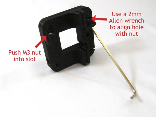
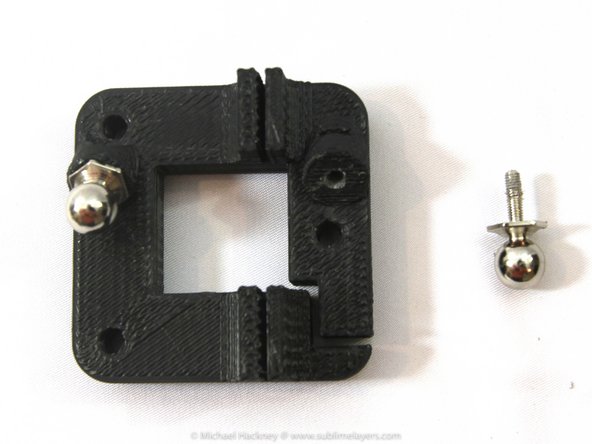
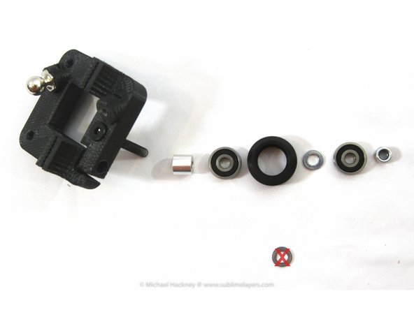
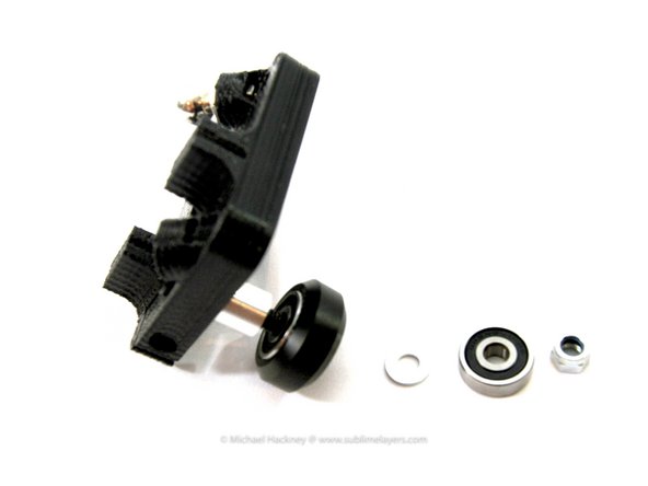
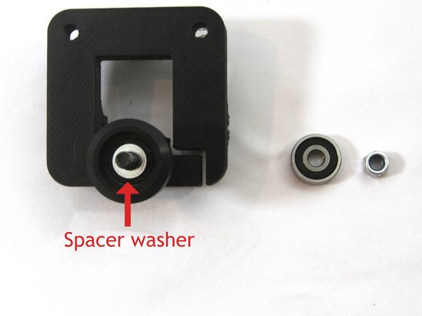
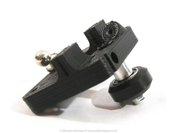
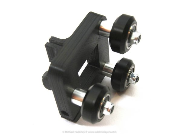
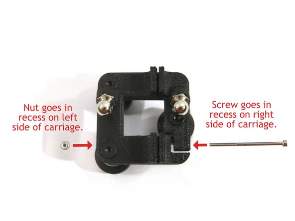
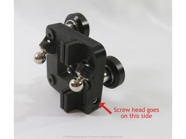
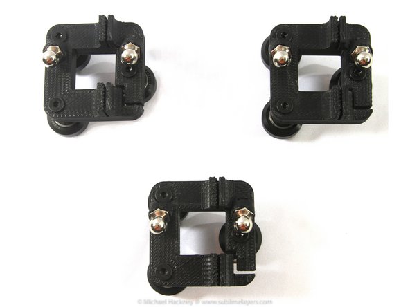
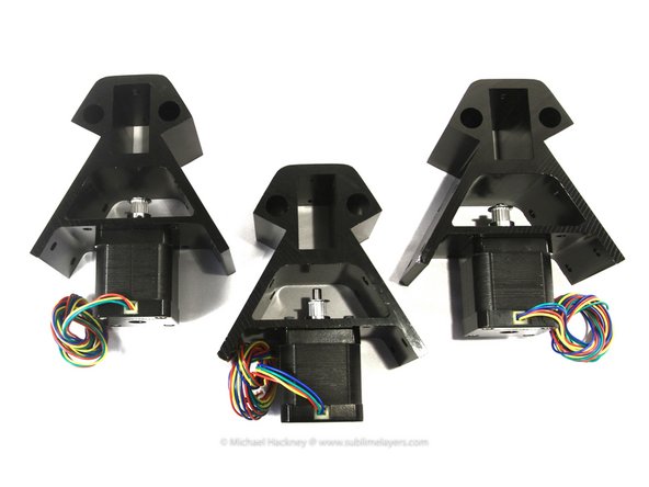
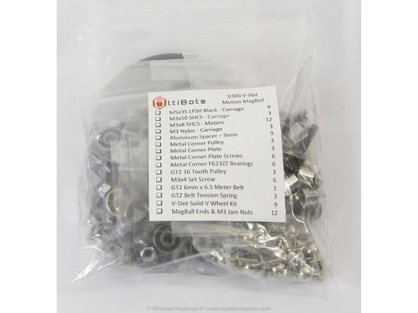
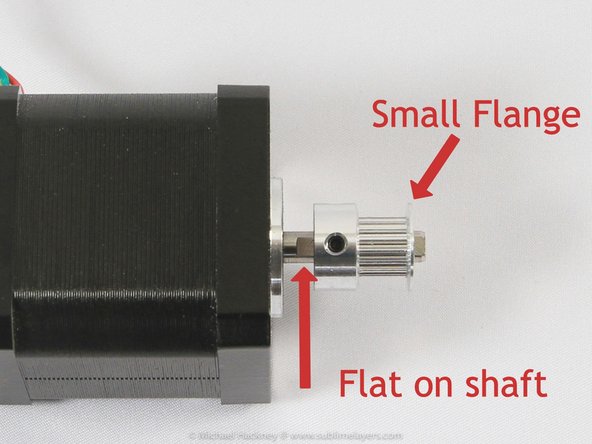
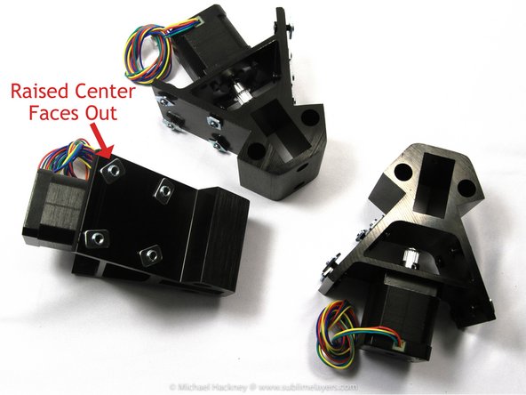
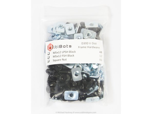
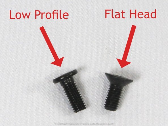
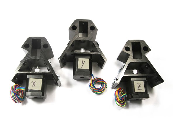
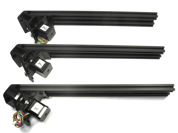
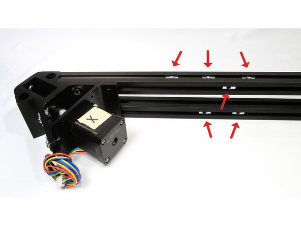
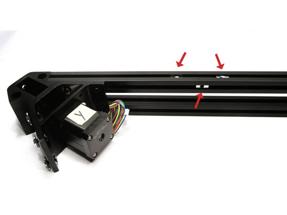
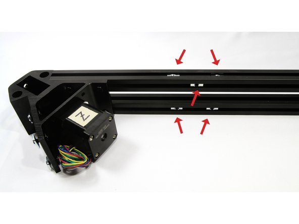
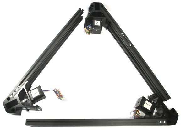
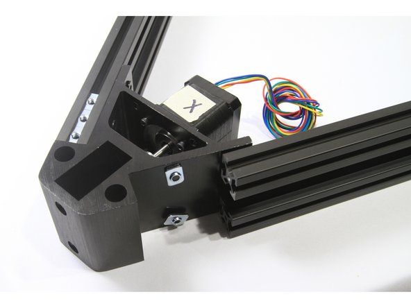
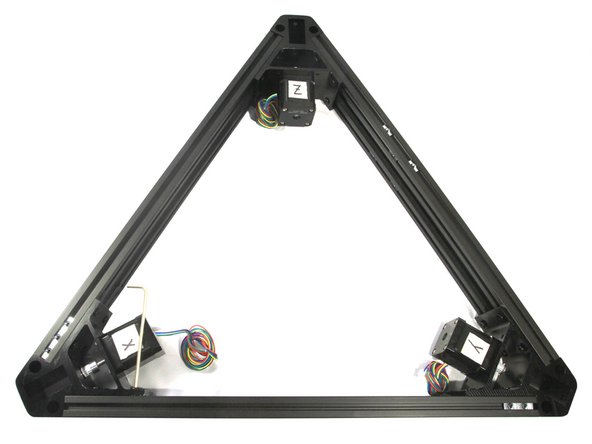
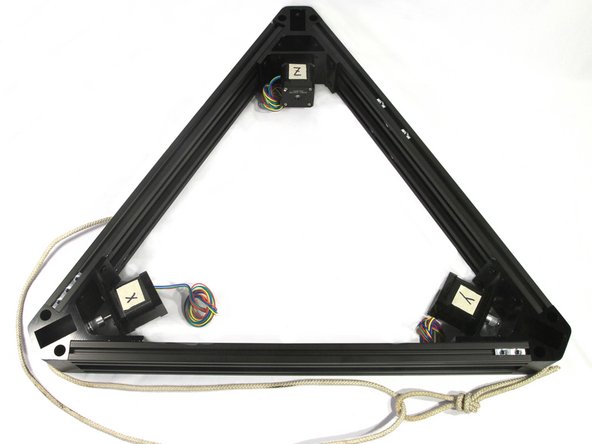
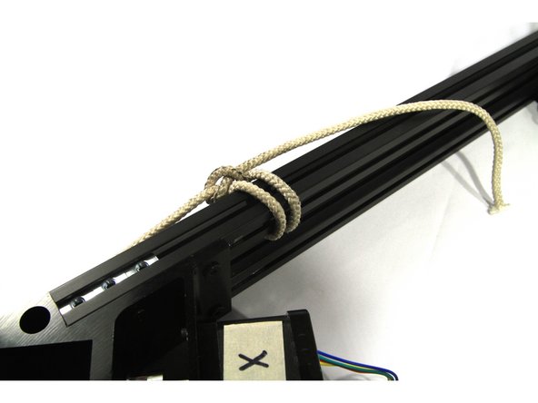
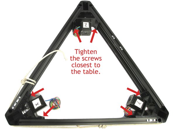
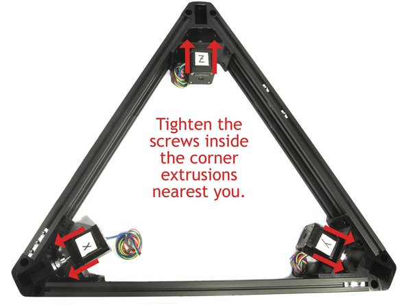
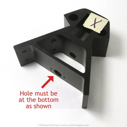
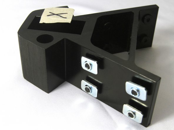
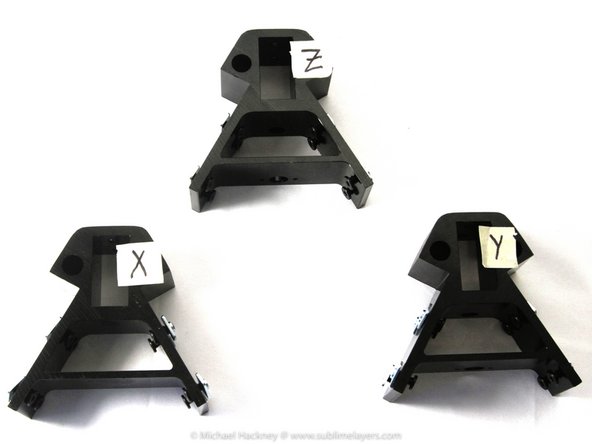
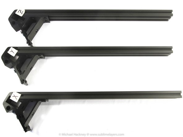
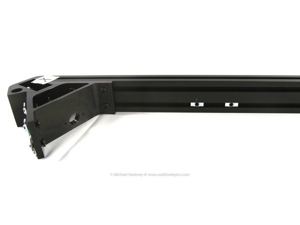
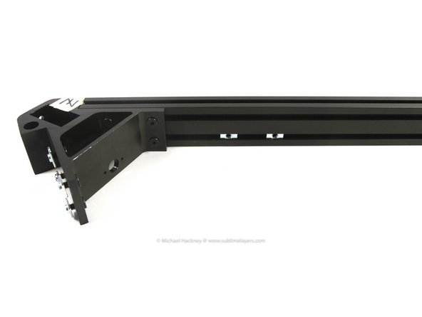
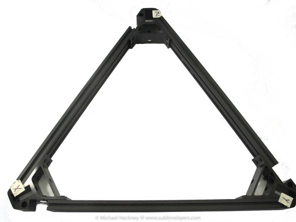
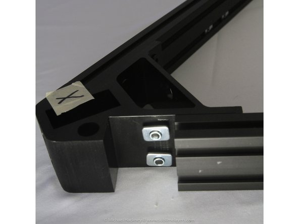
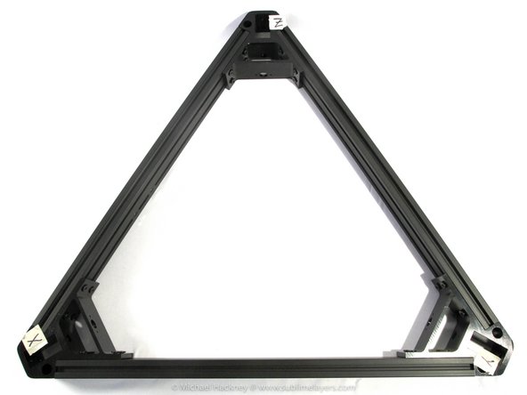
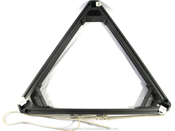
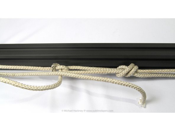
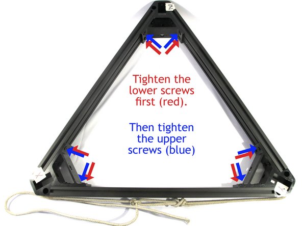
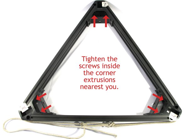
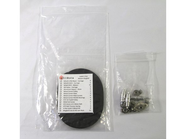
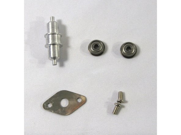
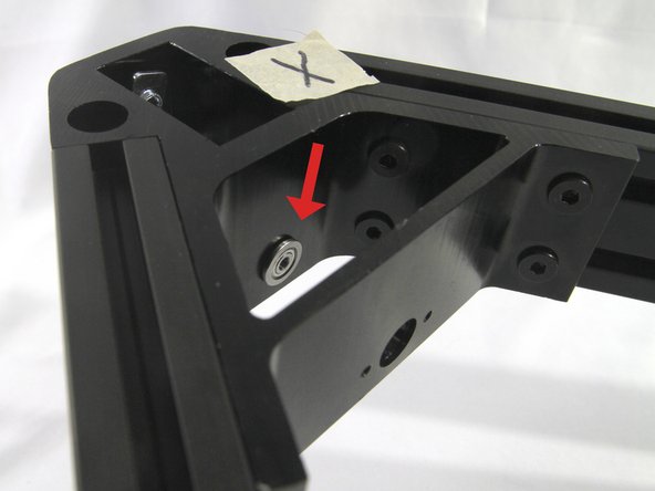
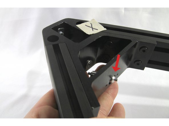
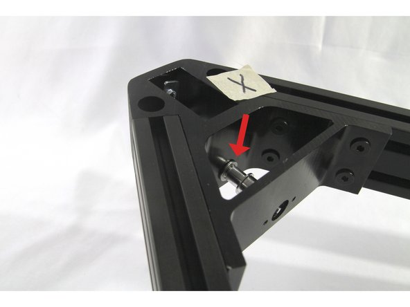
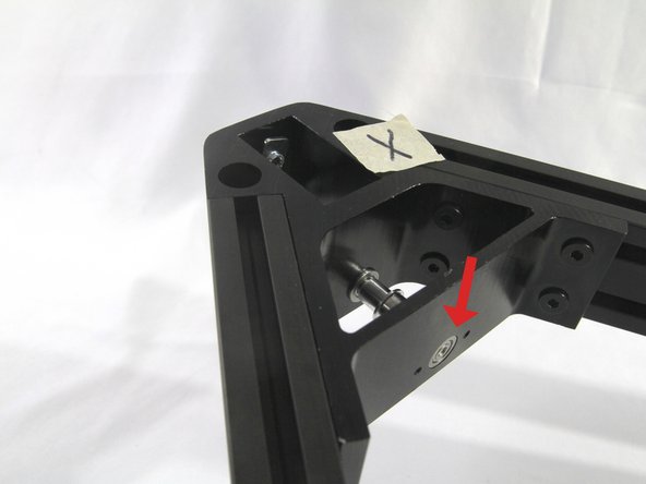
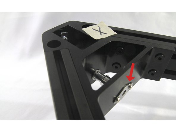
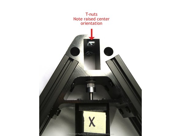
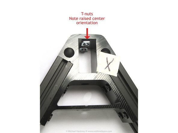
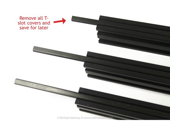
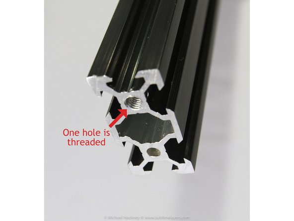
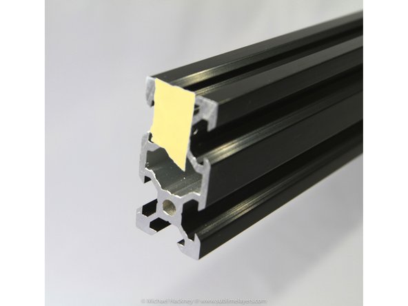
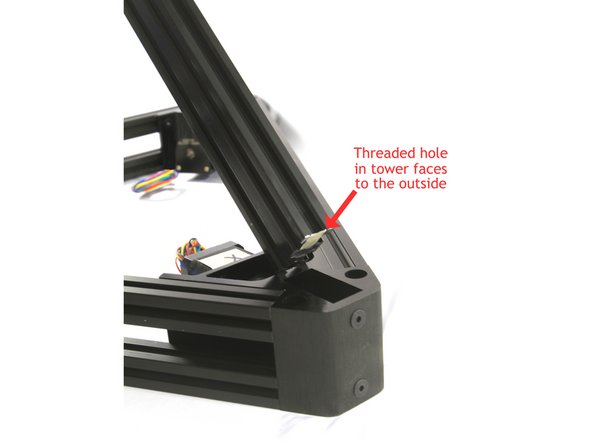
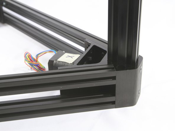
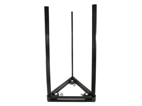
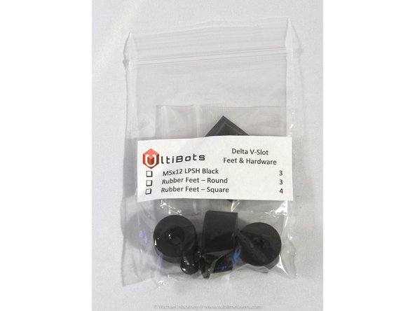
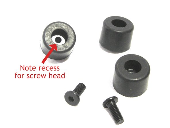
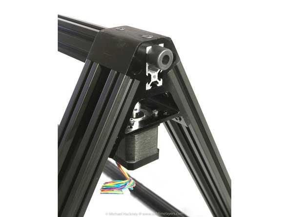
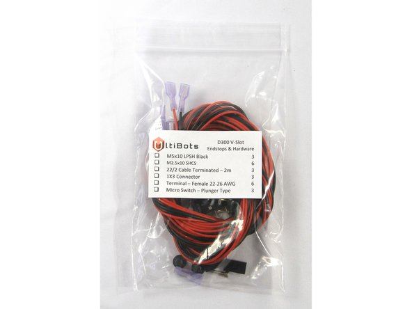
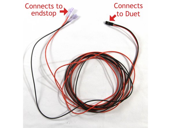
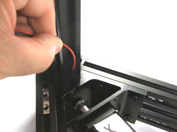
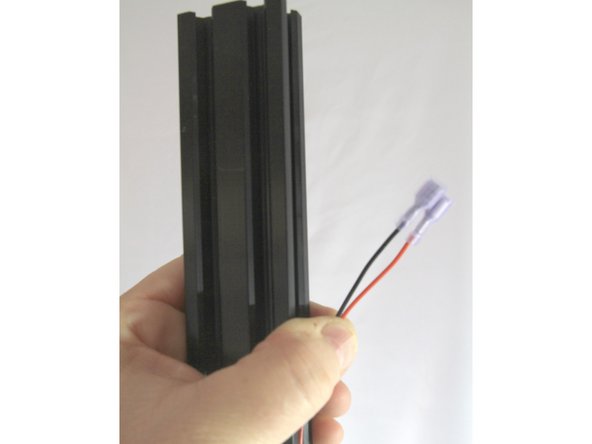
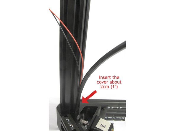
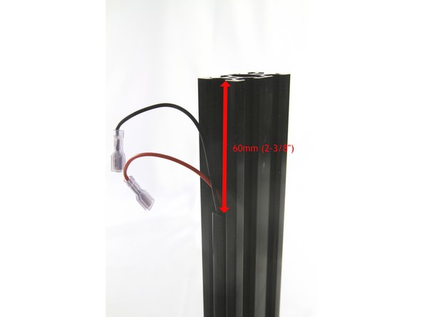
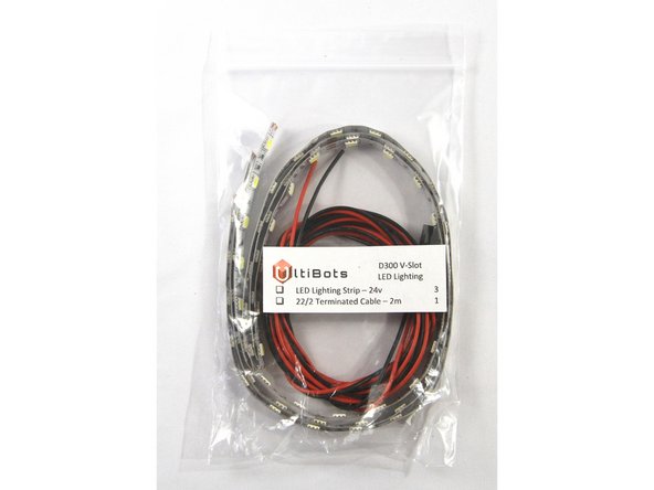
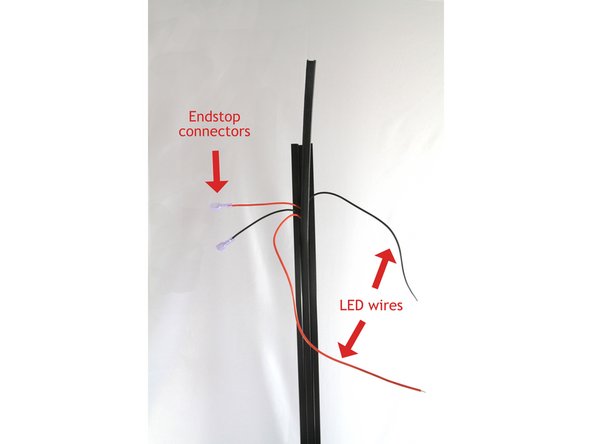
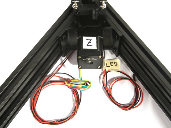
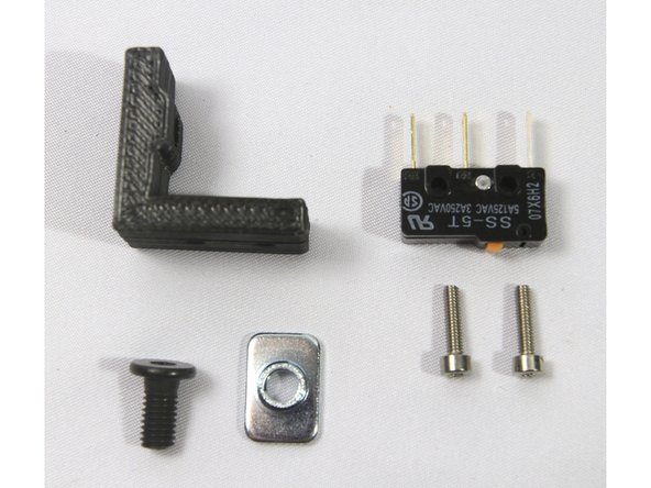
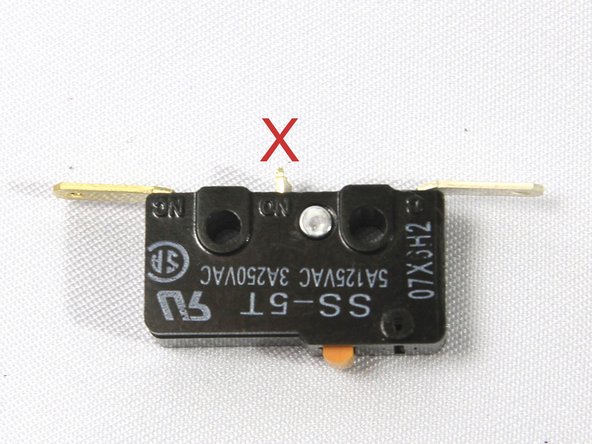
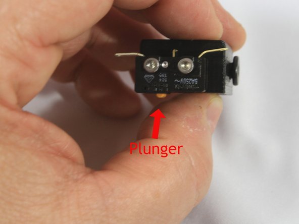
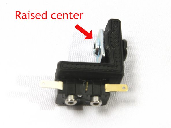
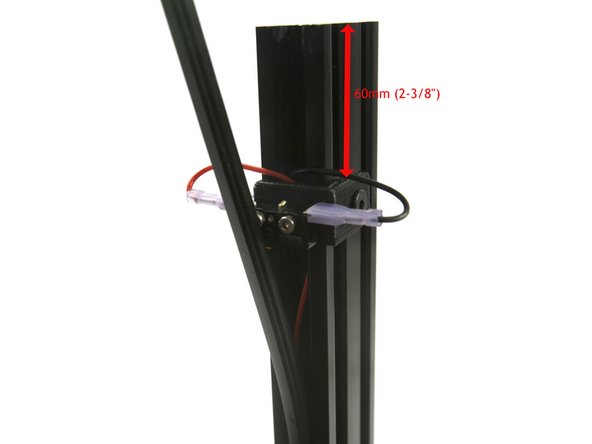
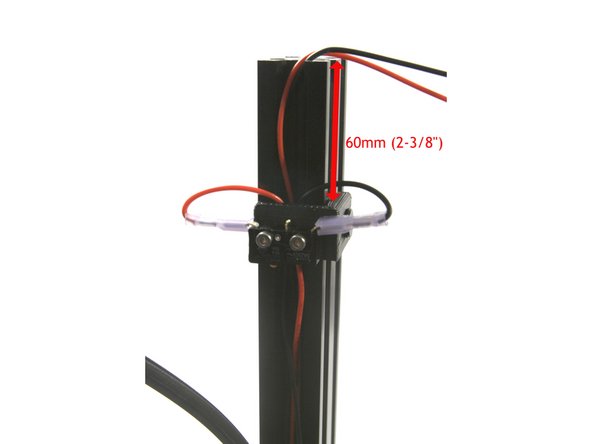
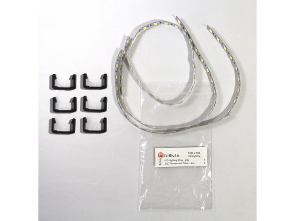
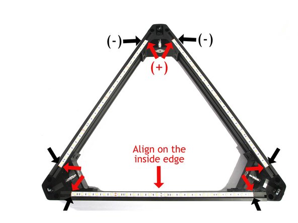
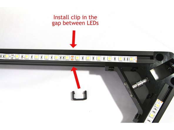
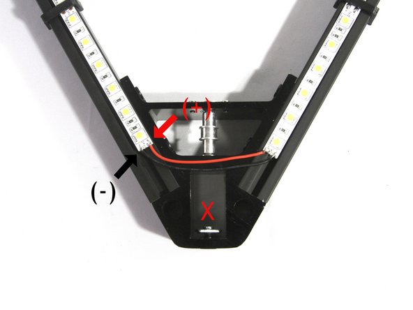
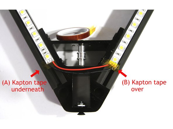
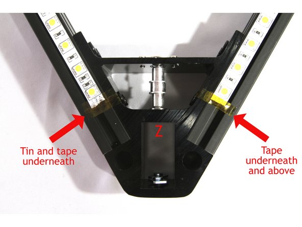
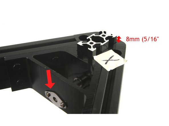
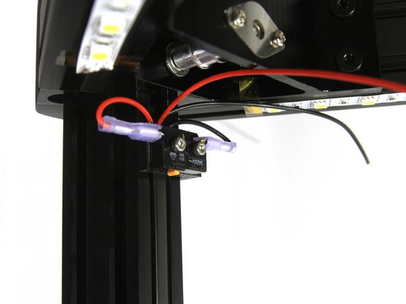
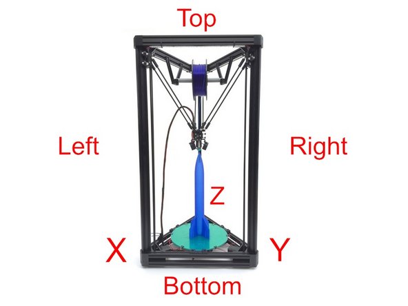
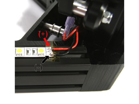
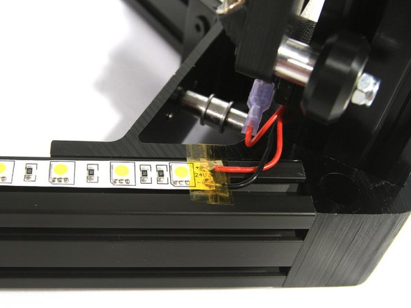
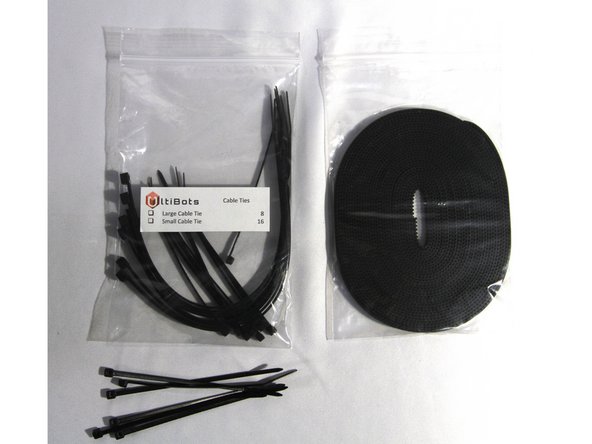
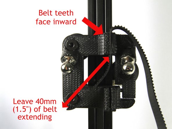
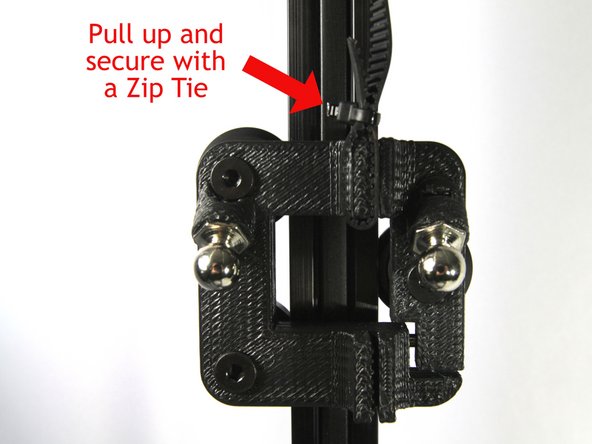
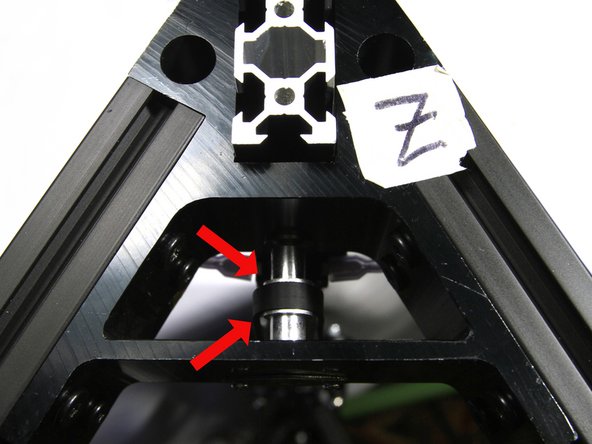
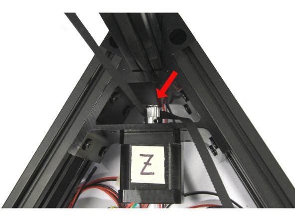
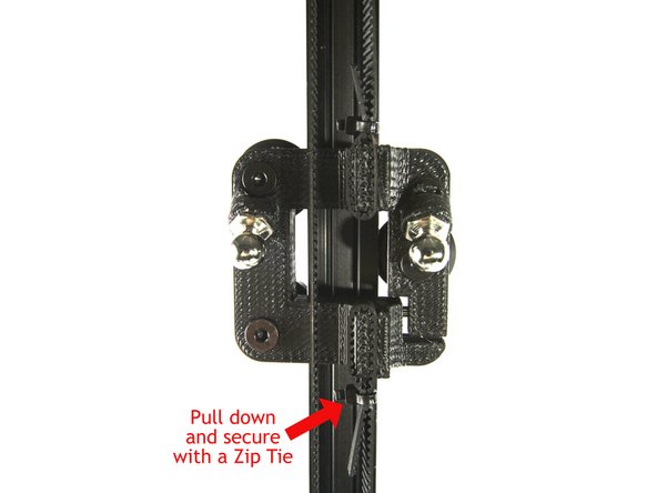
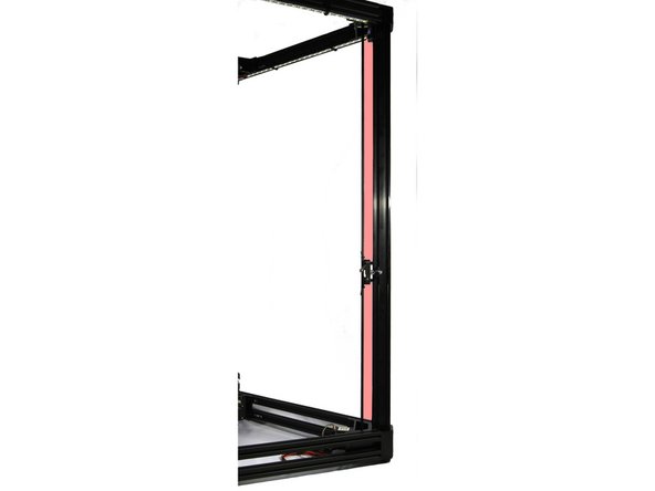
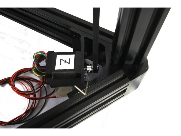
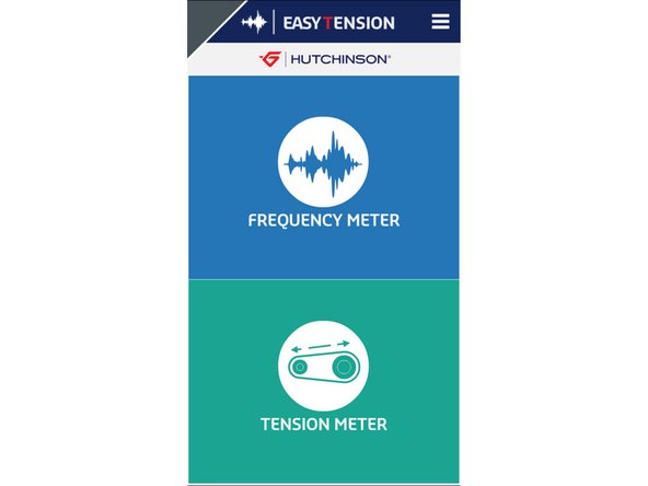
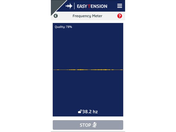
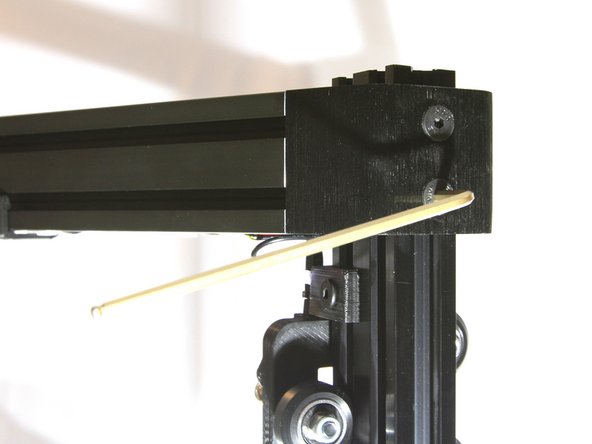
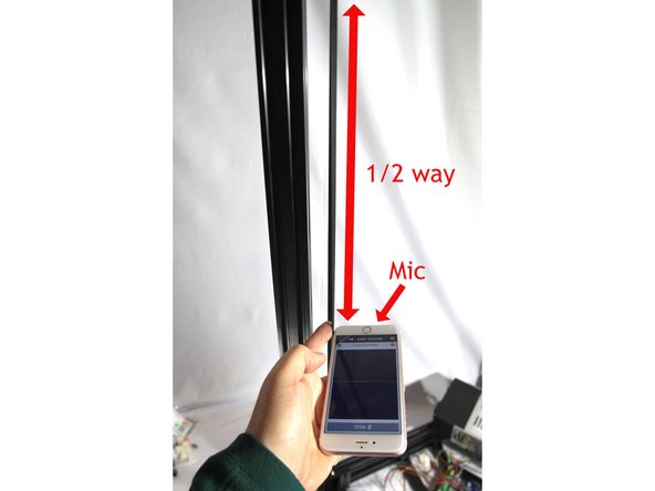
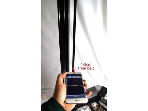
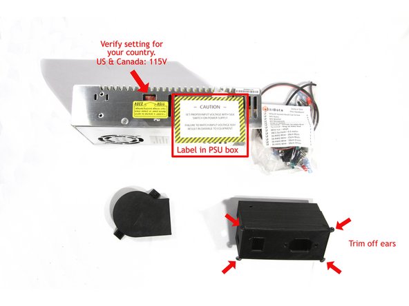
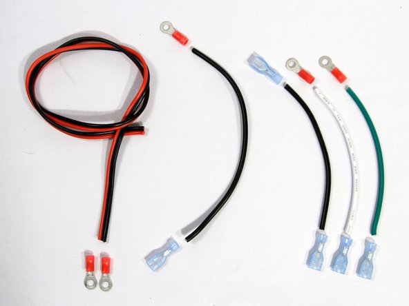
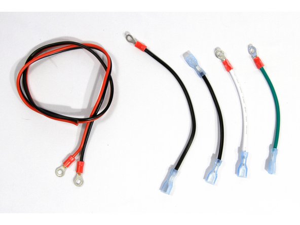
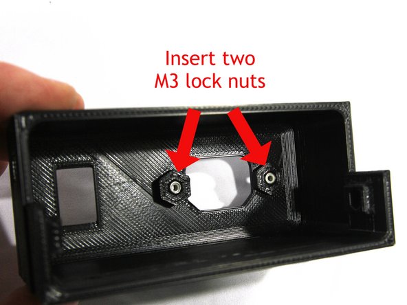
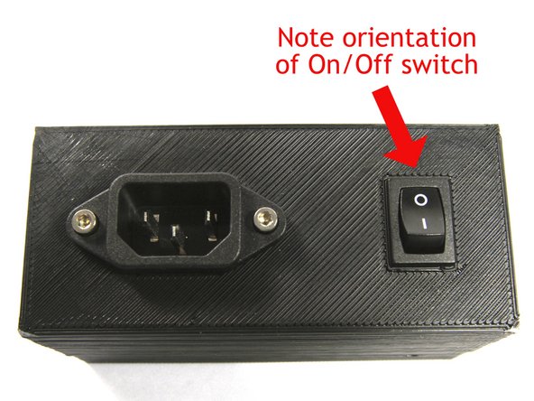
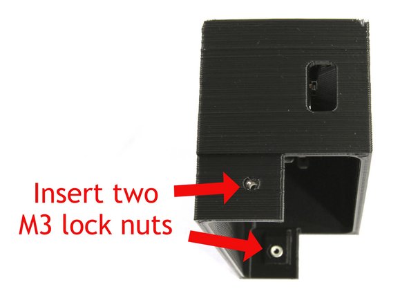
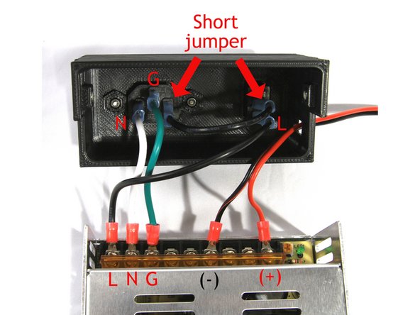
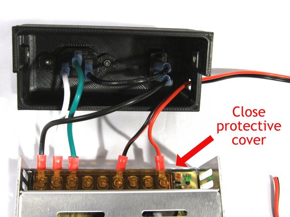
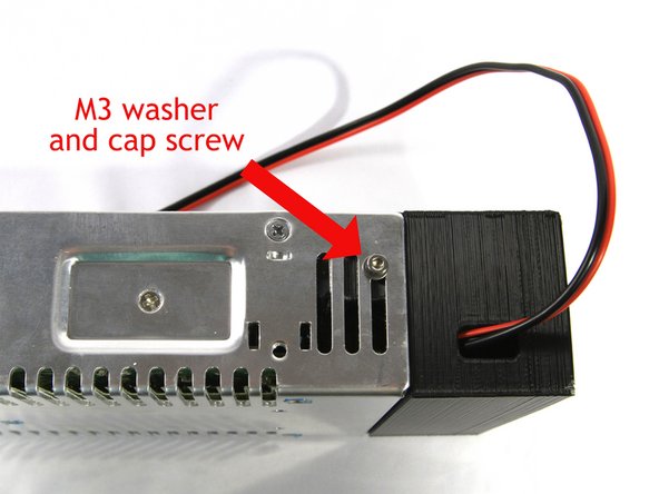
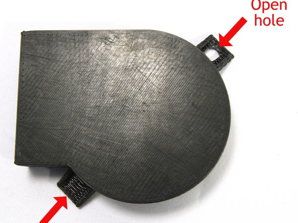
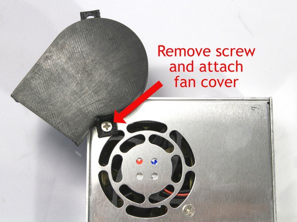
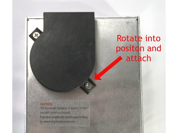
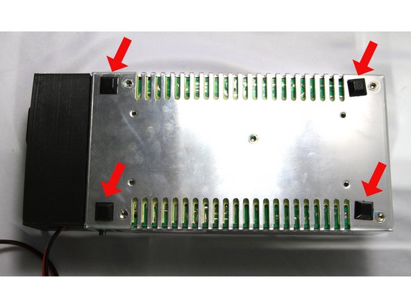
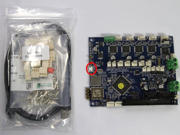
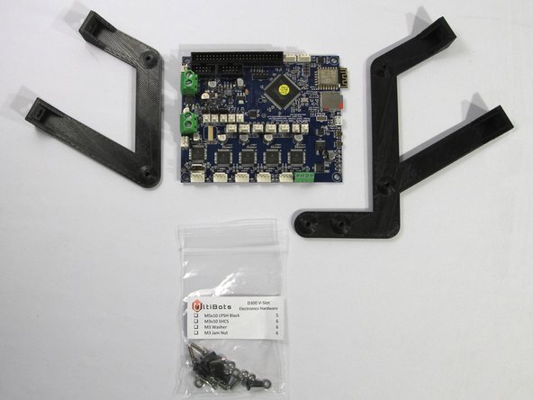
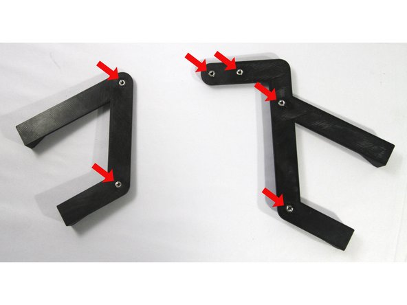
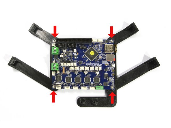
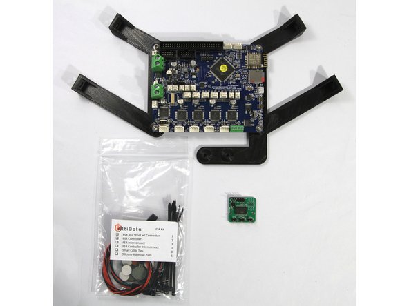
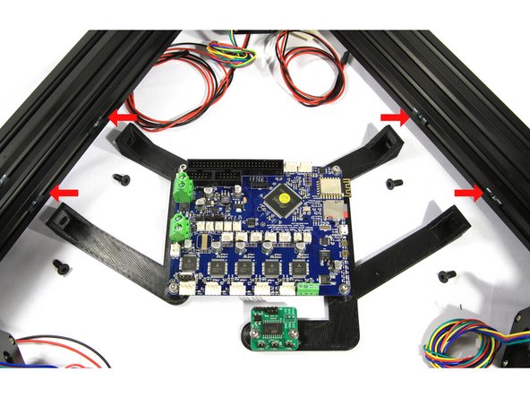
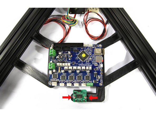
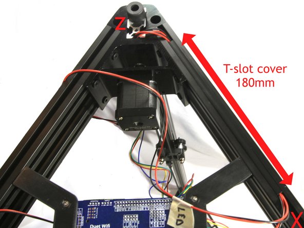
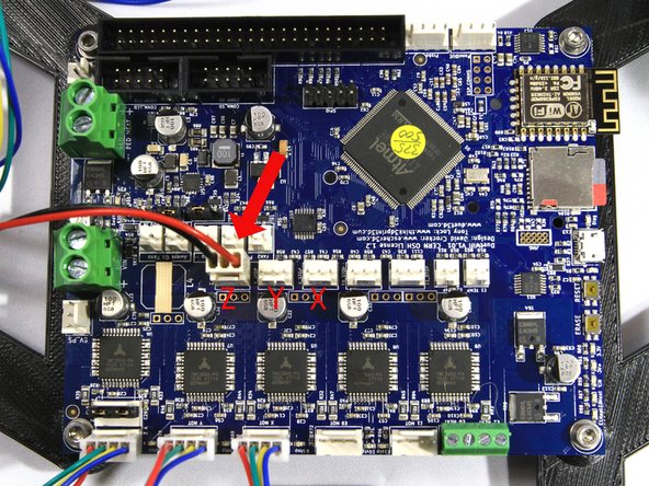
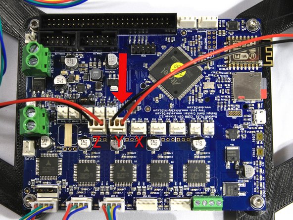
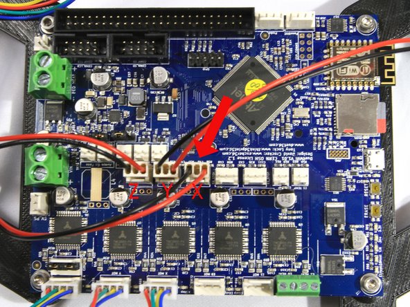
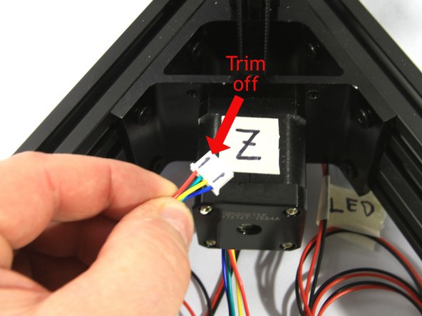
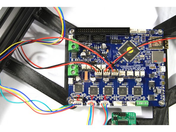
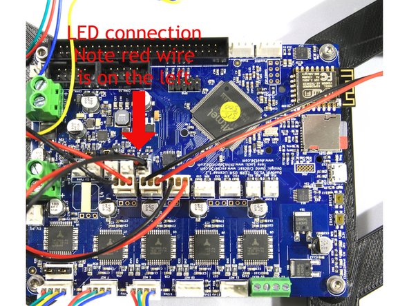
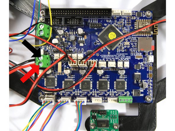
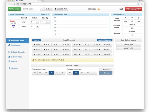
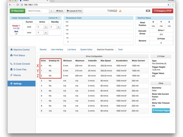
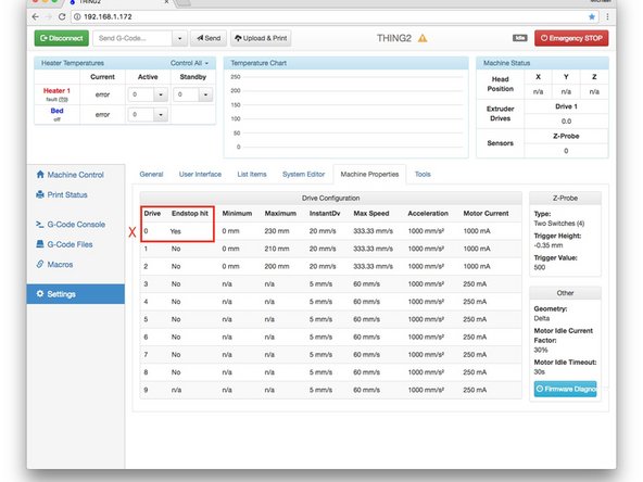
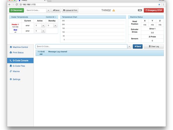
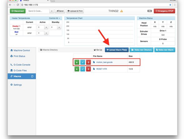
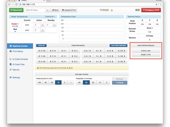
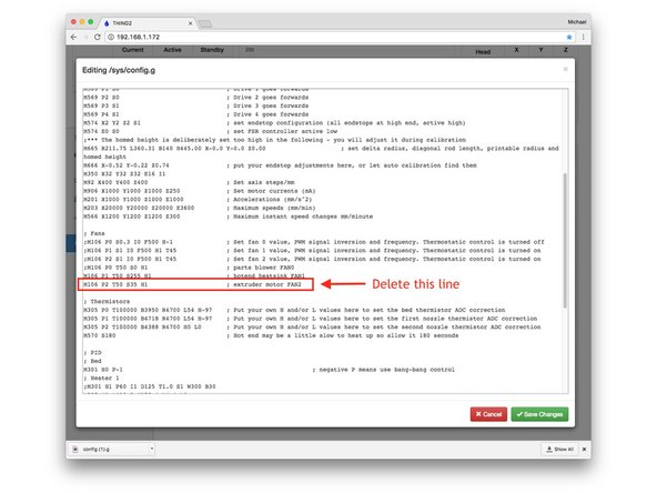
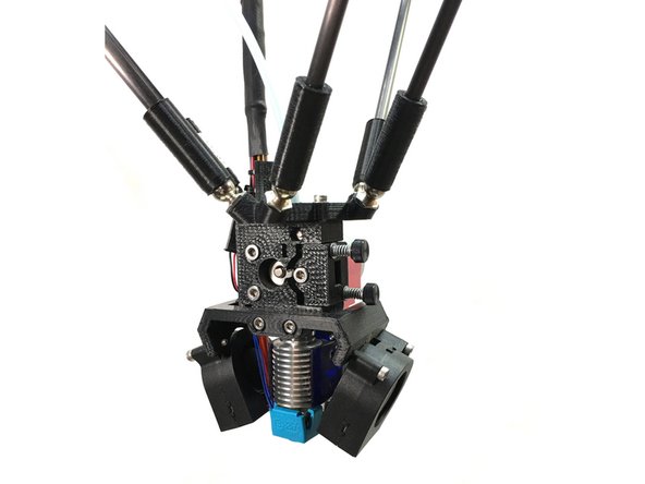
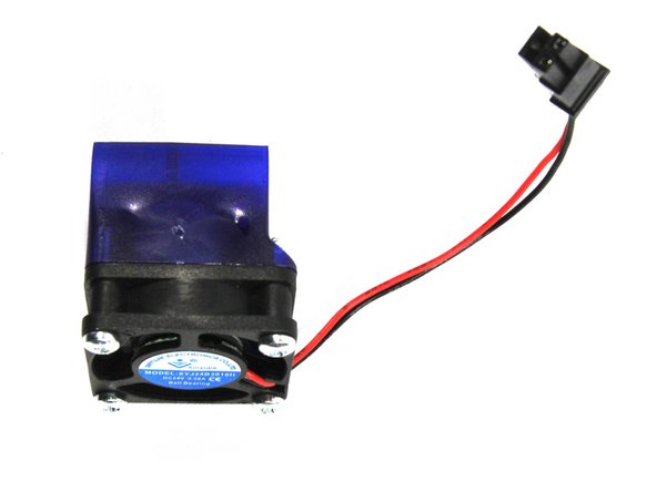
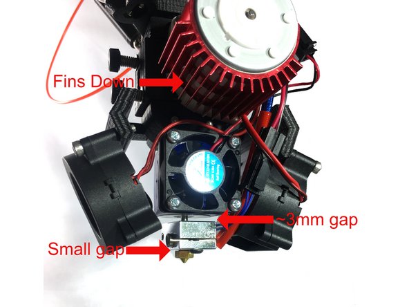
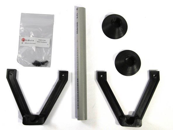
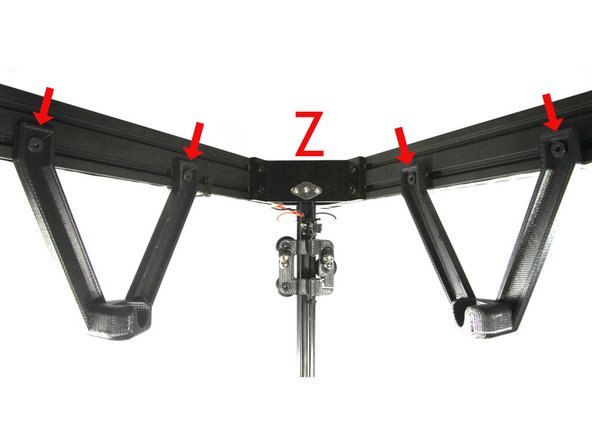
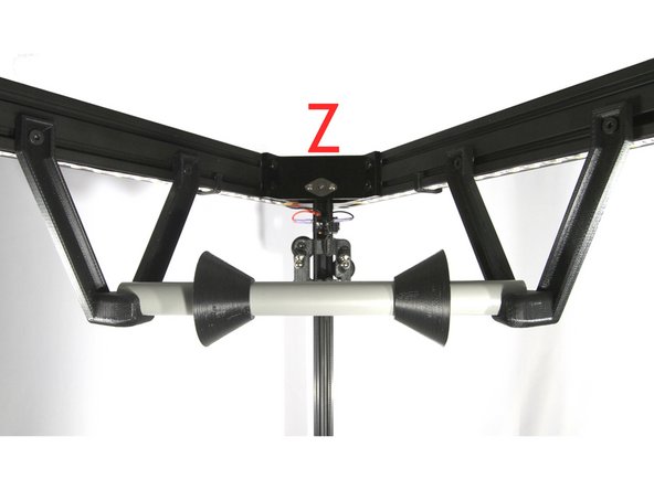
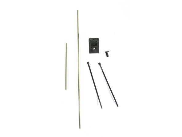
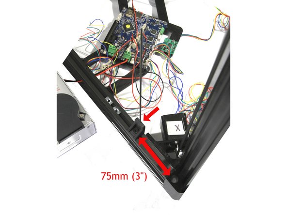
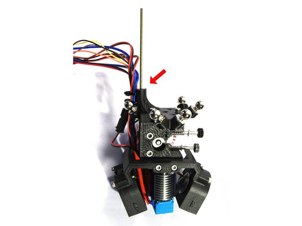
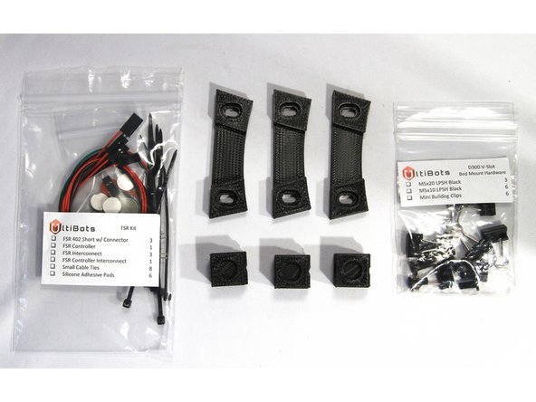
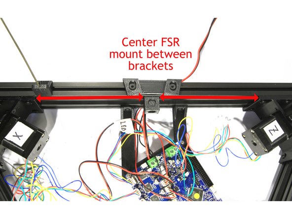
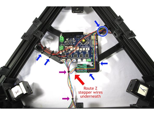
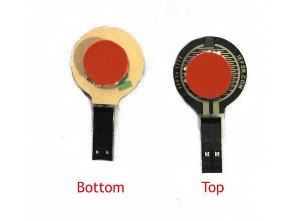
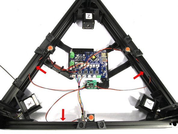
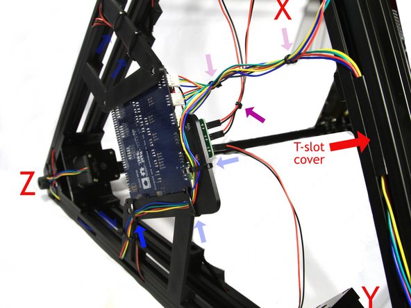
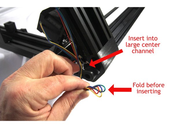
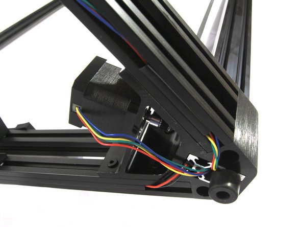
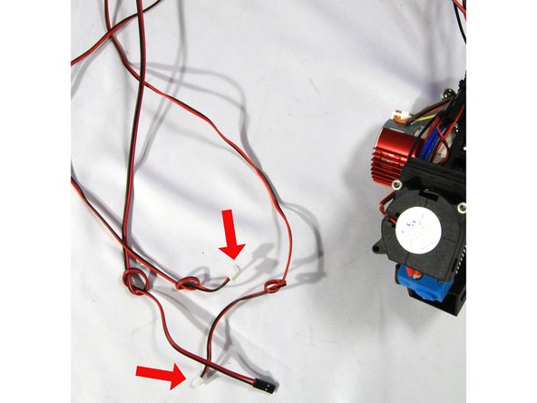
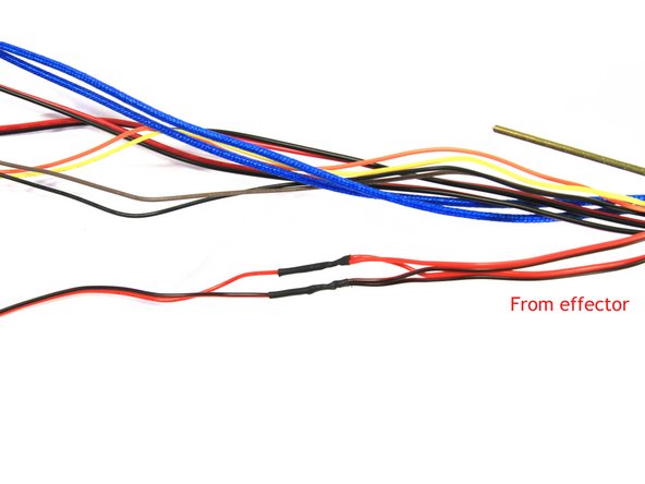
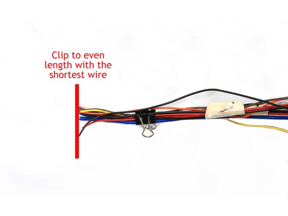
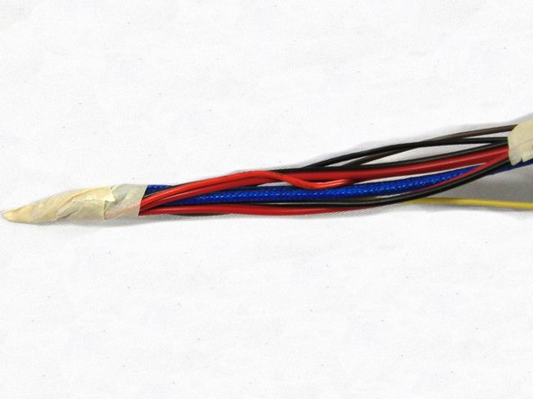
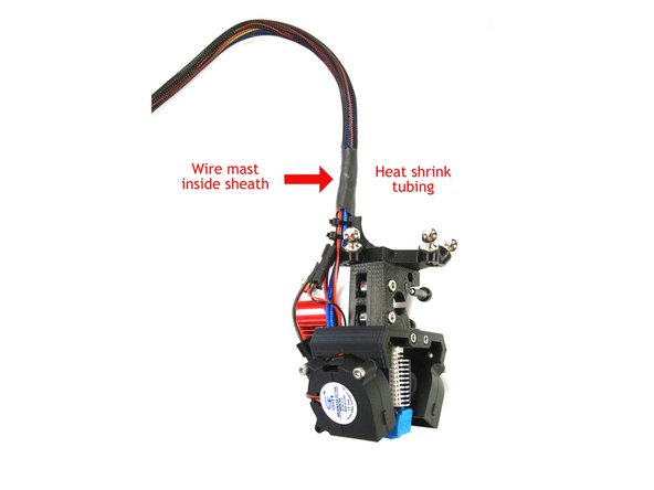
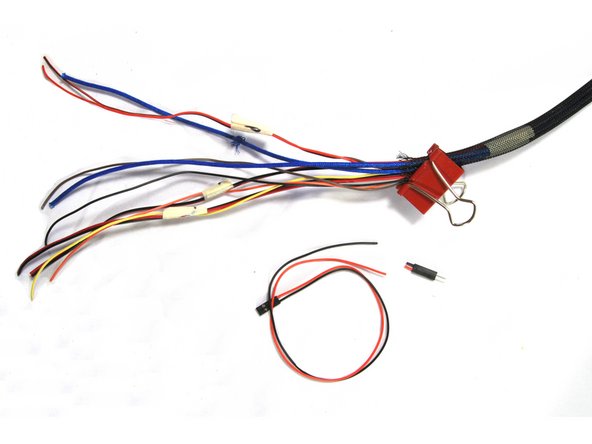
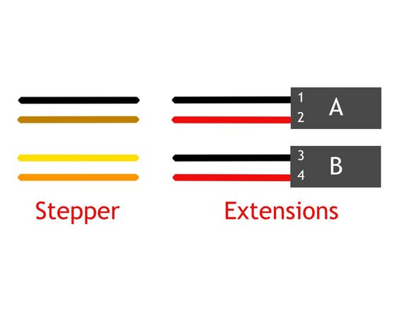
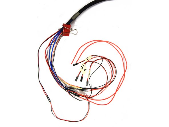
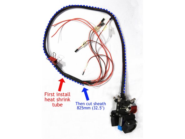
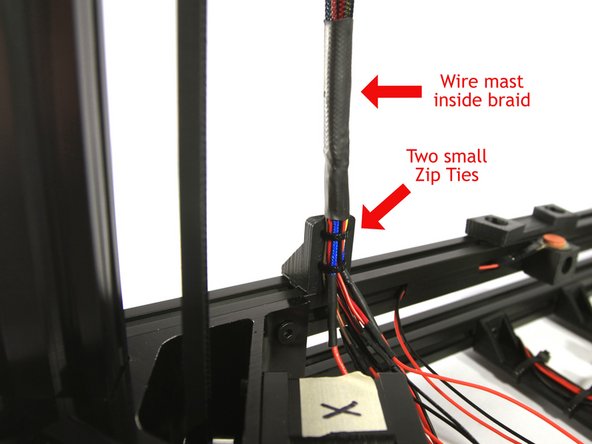
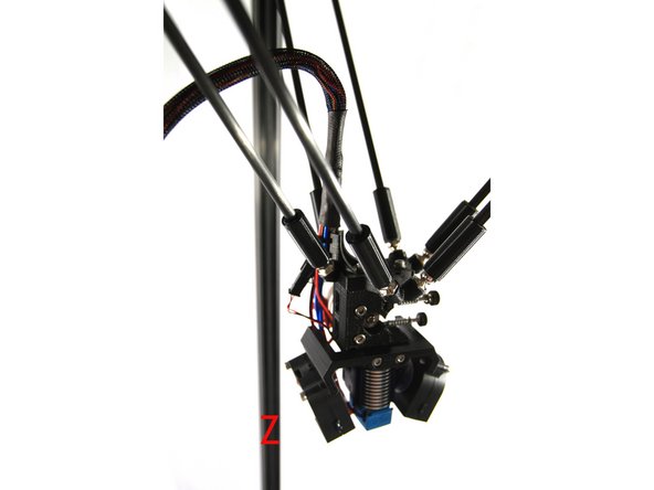
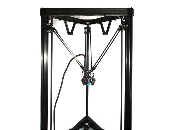
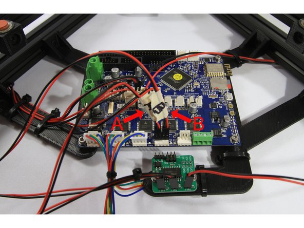
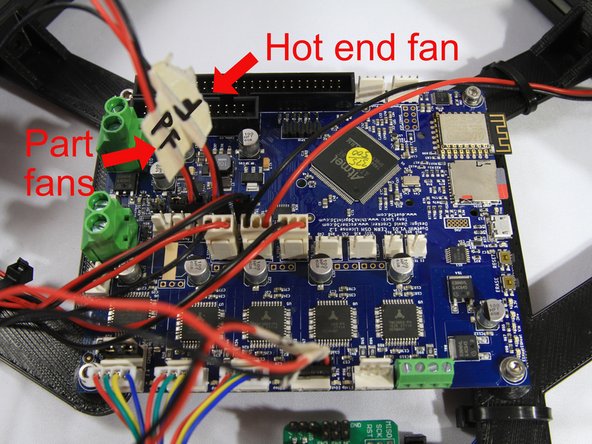
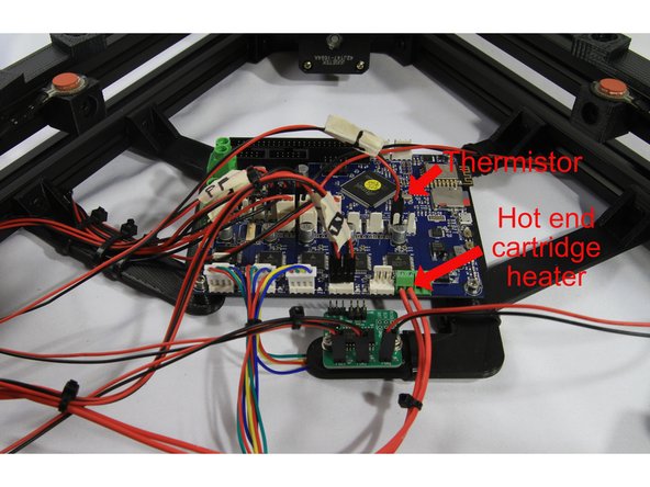
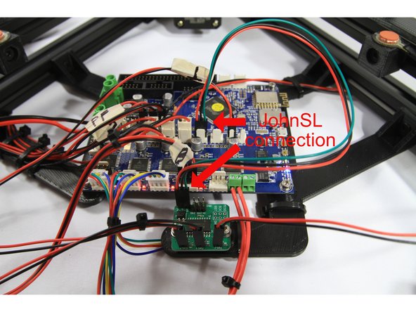
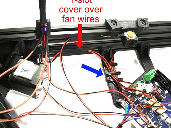
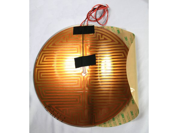
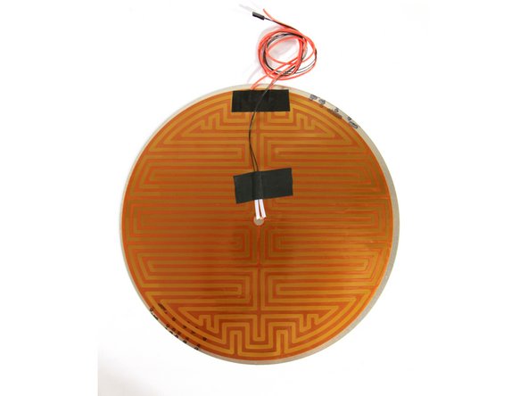
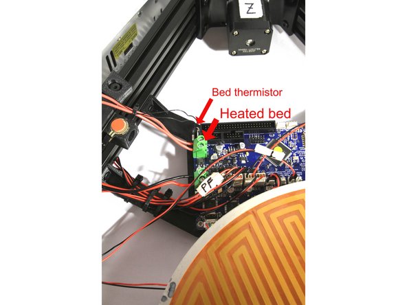
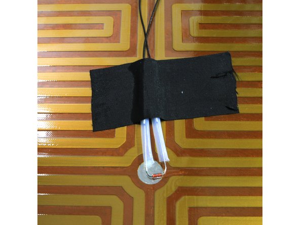
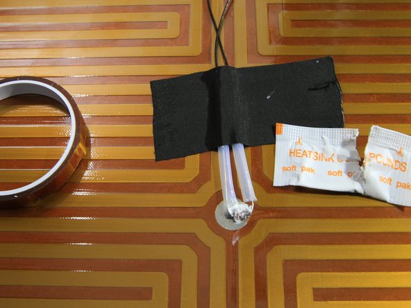
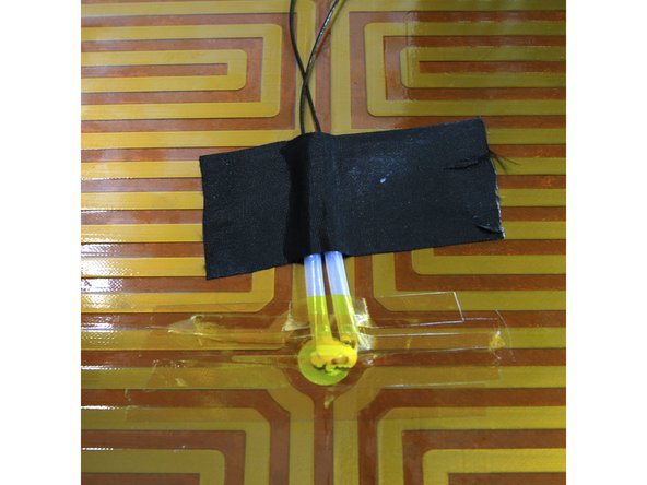
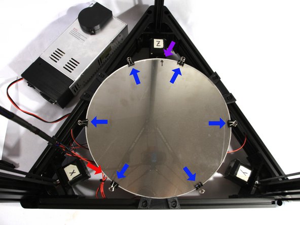
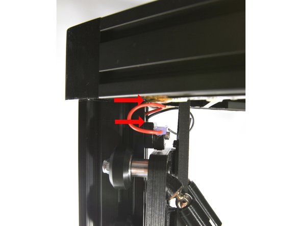
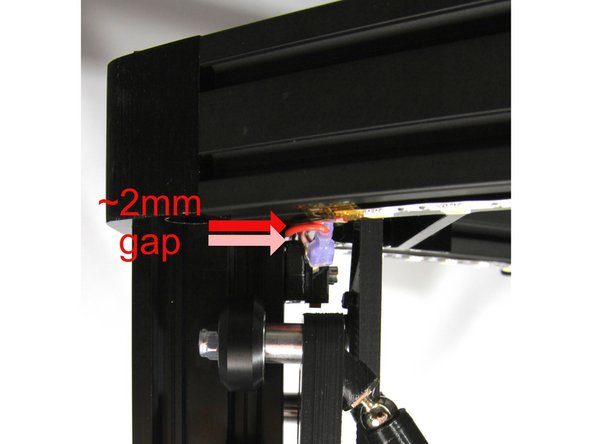

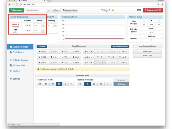
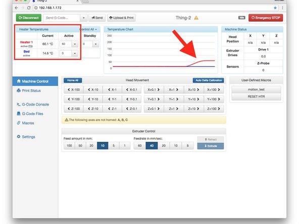
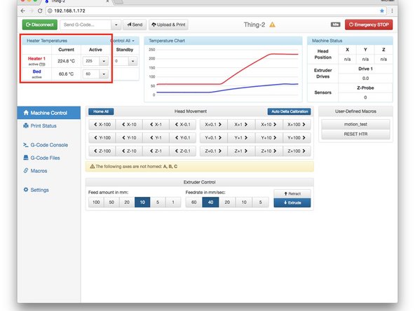
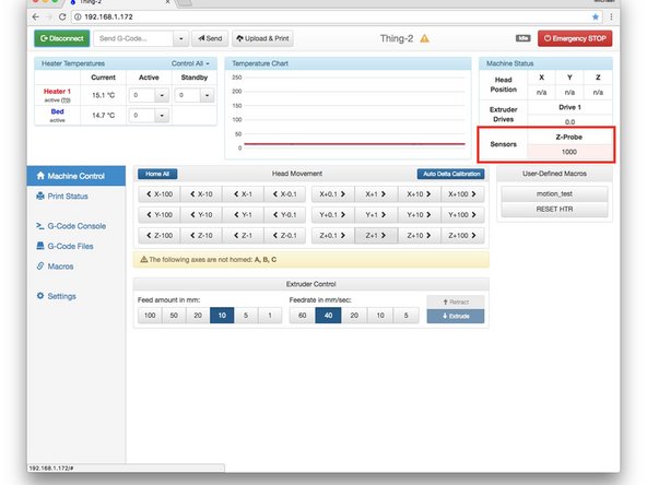
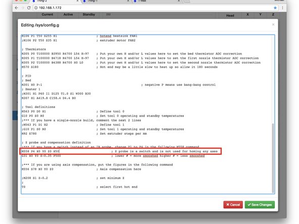
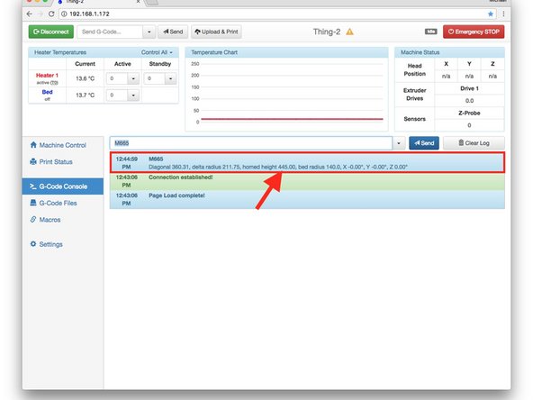
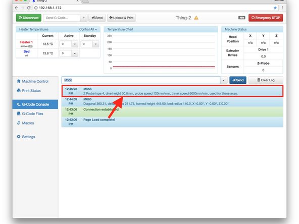
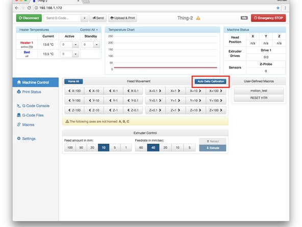
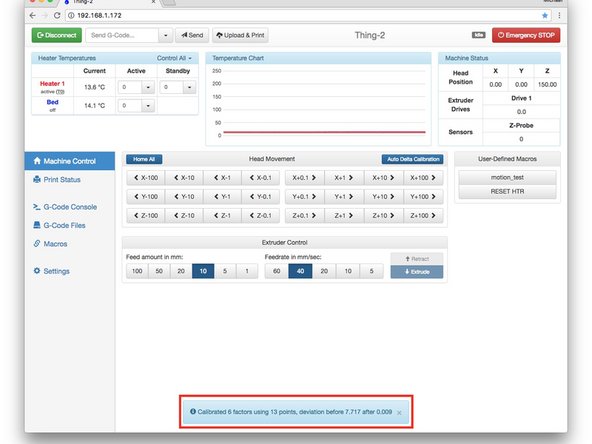
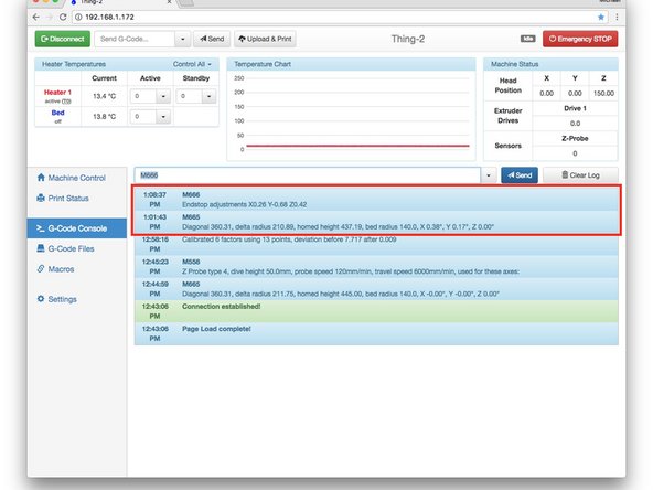
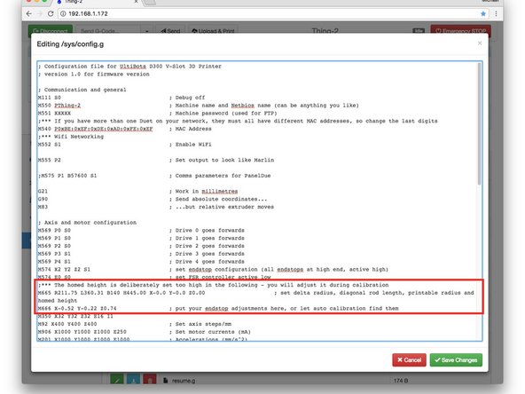
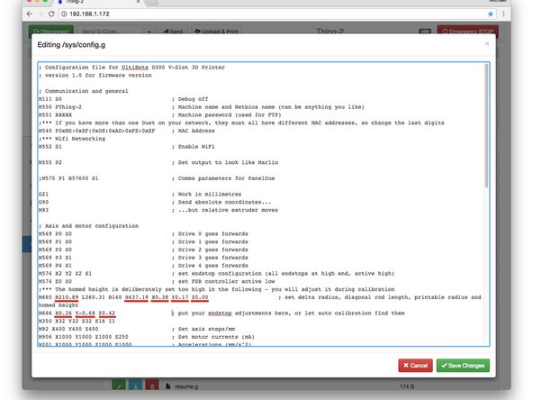
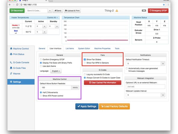
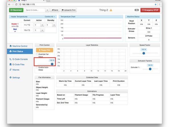
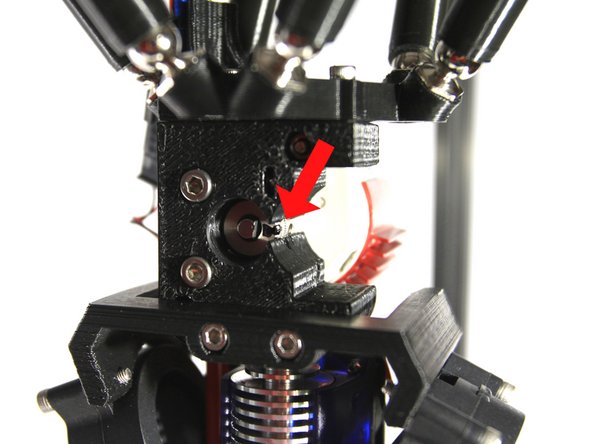
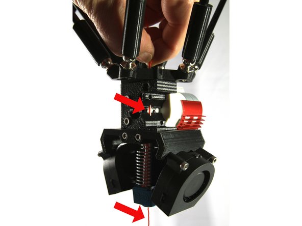
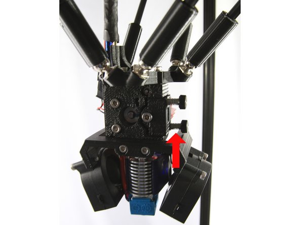
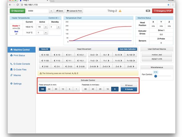
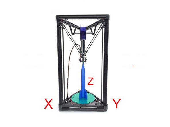
Note that you will likely have parts like screws, nuts, washers, various electrical connectors and others. You just need to have the parts called out in the Build Guide!
Note that you will likely have parts like screws, nuts, washers, various electrical connectors and others. You just need to have the parts called out in the Build Guide!
Cancel: I did not complete this guide.
6 other people completed this guide.