
-
-
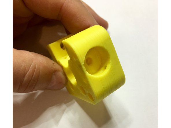
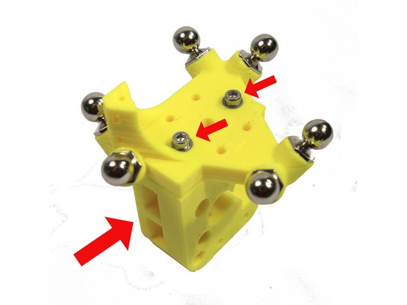
Note that your extruder will be printed in black ABS. The printed parts used in this guide are printed in yellow ABS in order to highlight their details. These parts were also printed rather quickly and may appear a little "rougher" than your production parts.
-
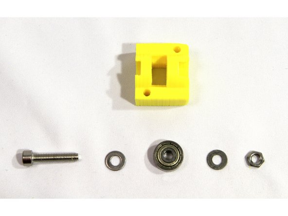
The second photo shows the parts required for assembly. Note the aluminum heat sink in your kit will be black instead of the red one used here for clarity in the photos.
-
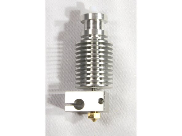
Please read the E3D V6 Assembly Guide before starting assembly of the hot end. Note that we do put the fan on opposite of how E3D installs. That's so the fan air flow is more effectively cooling the Micro Extruder stepper motor.
-
-
-
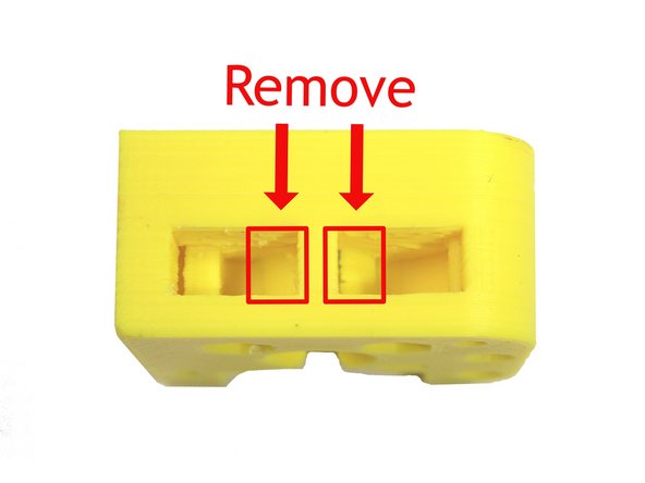
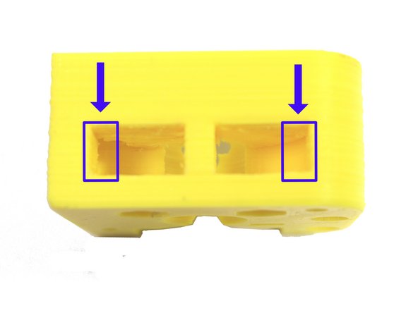
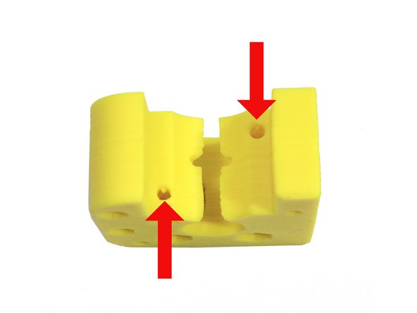
Remove the two supports highlighted in red from the extruder body using a sharp X-acto knife. Remove the single highlighted support from the idler.
-
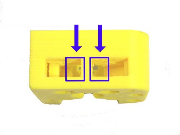
Clean up the openings as shown in the second photo.
-
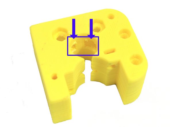
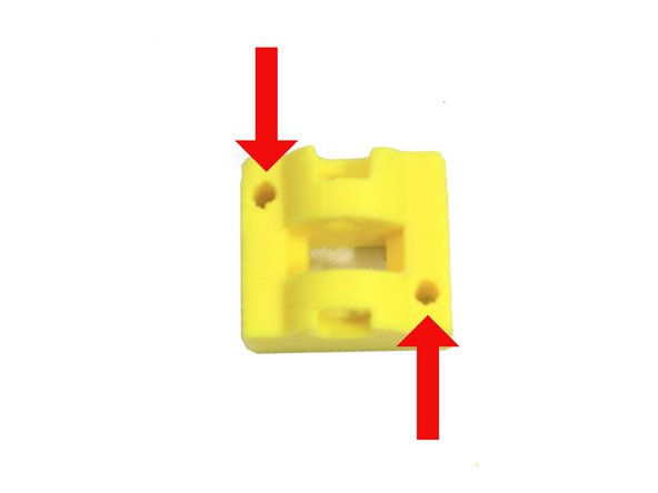
Next clean out the four holes on the extruder body and the support on the back side of the idler as shown in the third photo.
-
-
-
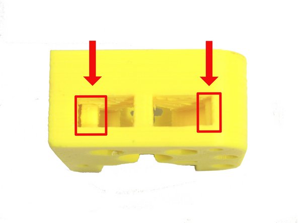
Remove the two highlighted support structures. These are easiest to remove through the openings exposed in the previous step as shown here.
-
The second and third photos show the support removed.
-
-
-
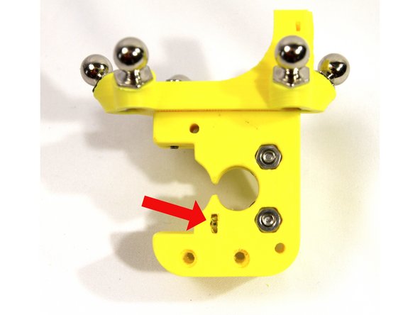
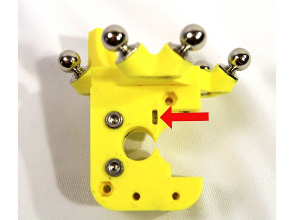
Remove the screw hole supports highlighted in red.
-
The second photo shows the supports removed.
-
-
-
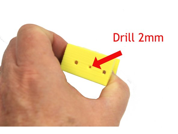
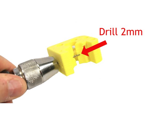
Use a 2mm drill bit in either a pin vise or electric drill to ream the filament path in the extruder body.
-
Make sure to ream all the way through from both directions as shown in the second photo.
-
-
-
Remove the idler nut support. The photo shows the support removed.
-
-
-
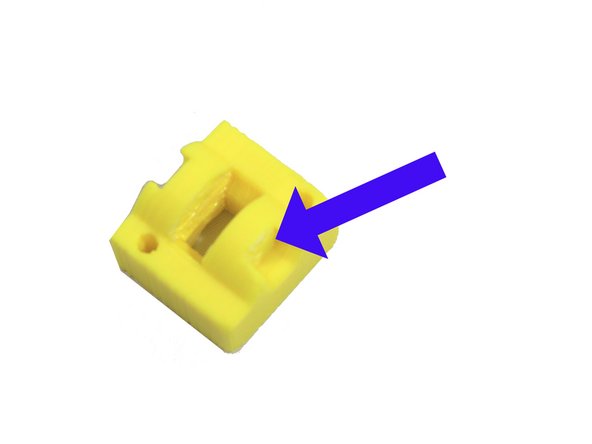
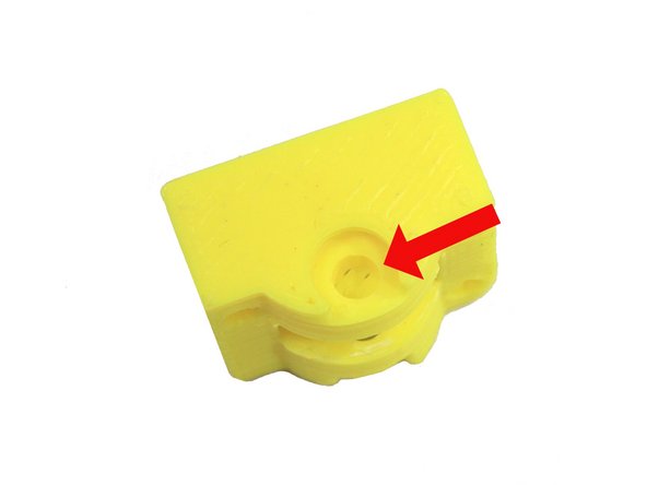
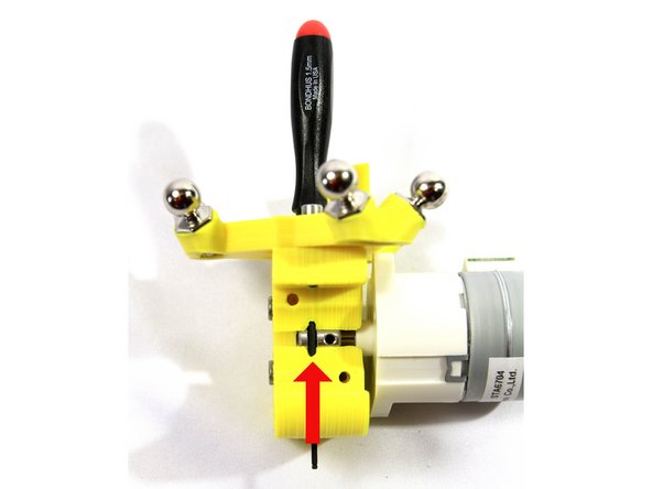
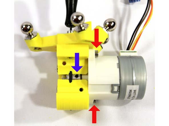
The through hole on the idler is blocked by a support on each side. The first photo shows one of these supports.
-
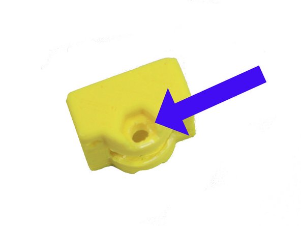
Remove the support on one side of the idler as indicated by the blue arrow in the second photo.
-
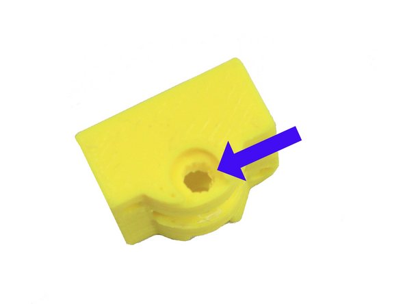
Remove the second support on the other side of the idler as indicated by the blue arrow in the third photo.
-
-
-
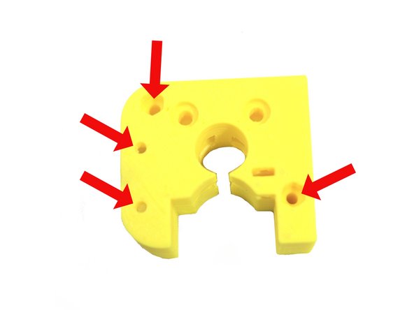
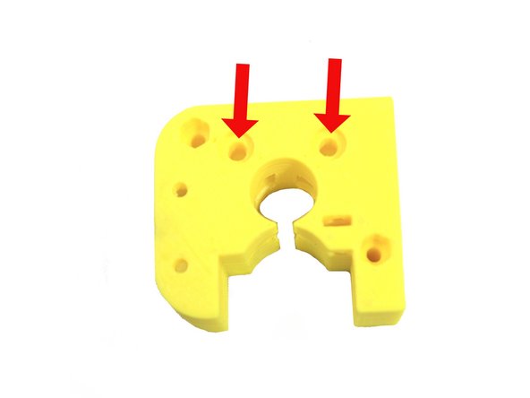
Use a 3mm to ream the four holes in the extruder body shown in the first photo.
-
Ream the two holes indicated in the second photo - do not drill past the nut trap slot.
-
Ream the two holes in the idler.
-
-
-
Ream the two bearing screw holes in the extruder body with a 4mm drill.
-
Ream the bearing screw hole in the idler with a 4mm drill as shown in the second photo.
-
Carefully look over both the extruder body and the idler and trim off and clean up any plastic remnants.
-
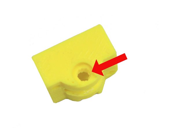
Make sure the E3D extruder recess (shown in third photo) does not have any plastic remnants or burrs.
-
-
-
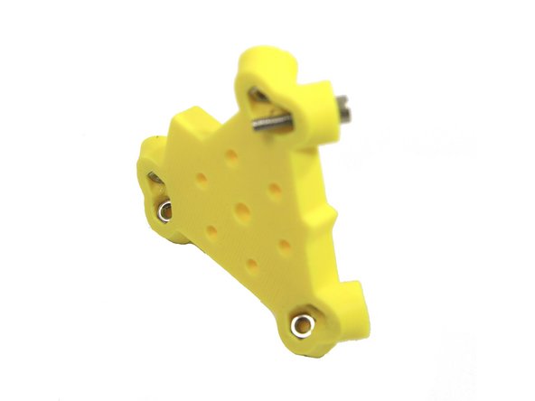
Do not ream the holes for the mag balls in the effector. They are designed to be a tight fit in order to maintain alignment.
-
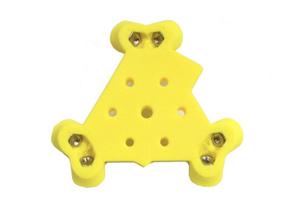
Install six M3 nuts into the six nut traps on the bottom of the effector.
-
Use an M3x16mm SHCS to draw and seat the nuts fully into the nut traps as shown in first and second photos.
-
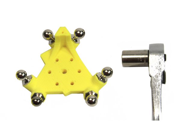
Screw the Mag Balls on finger tight.
-
Carefully tighten the Mag Balls with a 1/4 turn using a 10mm wrench or socket. Do not over tighten or you may strip the threads.
-
-
-
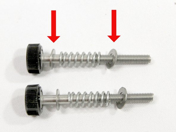
The black plastic thumbscrew is pre-attached to two screws. Add an M3 washer, spring and M3 washer to each as shown in the photo.
-
Set the idler tension screws aside for later.
-
-
-
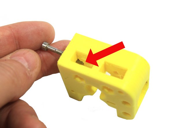
Inspect the extruder body as shown in the first photo. Temporarily inserting a screw as shown will help you visualize how the nut must be inserted into this slot. Remove the screw before inserting the nut!
-
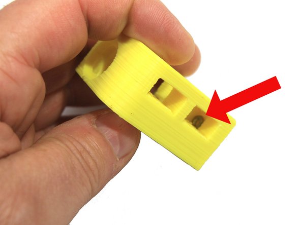
Insert an M3 nut into the slot inside the extruder body cavity. Use a small screwdriver to push it into position as shown. Check the alignment of the nut by looking thorough the hole. It it is not properly aligned, wiggle it into position with the screwdriver.
-
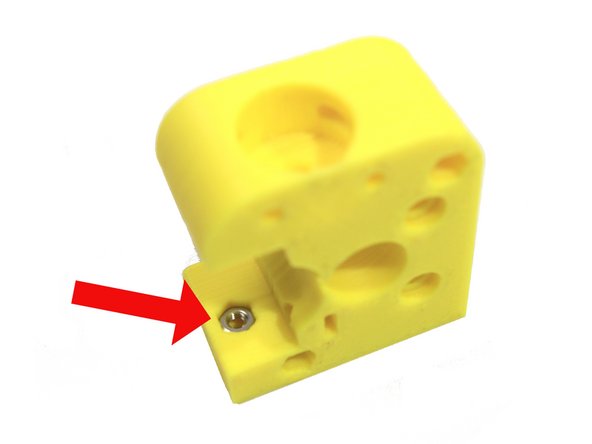
Insert a second M3 nut in the extruder body as shown in the third photo.
-
-
-
Attach the extruder body to the effector with two M3x16 screws and M3 washers as shown in the photo. The slots for the idler bearings must be oriented as shown.
-
Attach the screw that aligns with the captured nut you installed in the previous step first. Use a screw driver to help hold the nut in place and adjust its position if necessary.
-
Once the first screw is installed, install the second screw. Then tighten both screws securely.
-
-
-
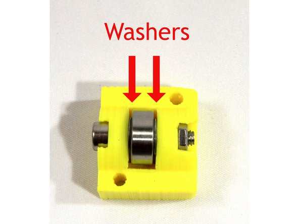
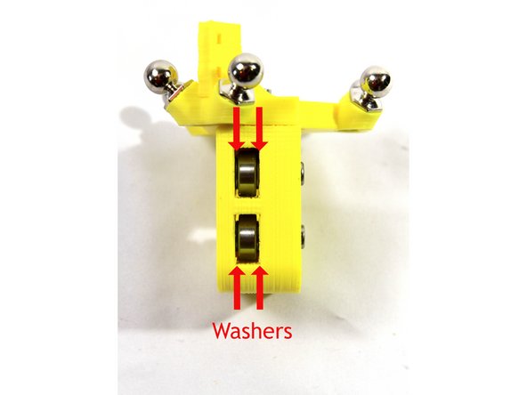
Insert one 624ZZ bearing with an M4 washer on either side into the bearing slots in the idler as shown in the first and second photos.
-
Use an Allen wrench to align the washers with the bearing hole and the holes in the idler.
-
Attach the bearing with an M4x20 SHCS and M4 nut as shown in the second photo,
-
Repeat the above steps to assemble the two bearings and washers in the bearing slots in the extruder body as shown in the third photo.
-
-
-
Install an M3 nut in each of the slots in the extruder body as shown in the photos.
-
If the nut is difficult to install, clean out any plastic debris with an X-acto knife.
-
-
-
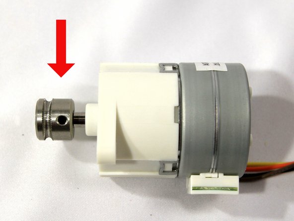
Install the drive gear on the stepper motor shaft with the set screw closest to the motor as shown in the photo.
-
Align the end of the drive gear with the end of the shaft.
-
Align the set screw with the flat on the stepper motor shaft and tighten the set screw with a 1.5mm Allen wrench.
-
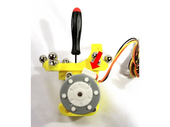
Rotate the drive gear (it will be hard to turn) to align the stepper motor as shown in the second photo. You want the set screw aligned with the extruder body slot and the stepper motor's mounting flanges aligned so that the wire harness comes out the top (the photo in the next step shows this more clearly).
-
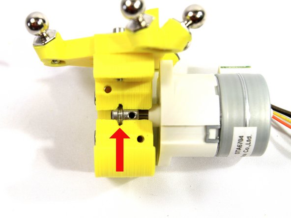
Insert the drive gear and stepper assembly into the extruder body. This is a tight fit and may require wiggling and some force. Don't push the gear and stepper all the way in, stop when the groove in the drive gear aligns with the filament guide in the extruder body as shown with the red arrow.
-
Loosen the set screw on the drive gear at least two complete turns. You need to loosen it enough that it won't interfere with the round part of the stepper shaft.
-
Insert a 1.5mm Allen wrench into the filament guide as shown in the third photo. This will help you align the drive gear groove and keep it in place while you install the stepper motor in the next step.
-
-
-
Hi All - NMB Minebea has made 2 PG35L motors for UltiBots. One with an 18mm shaft and the other with a 20mm shaft. We recently transitioned to the Motor with the 20mm shaft. As a result some kits shipped with a Micro Extruder Body that is not compatible with the longer motor shaft.
-
Kit owners with the PG35L-D48-UCH4A motor do NOT to use the "D Flat" for the set screw. UNLESS... your kit shipped after Aug 3rd, 2017. These kits have a compatible Micro Extruder body.
-
If your motor/body is not compatible... please apply one of the methods below to get your extruder assembled.
-
Rotate the drive gear so the set screw bites into the round part of the shaft.
-
Or if you have proper tools, extend the "D Flat" with a grinder or file. Don't let the shaft get too hot if grinding.
-
Or add 2-3 washers between motor body and extruder body. This provides set screw clearance on the "D Shaft".
-
-
-
Carefully push the stepper motor all the way to the extruder body. Attach it to the extruder body with two M3x25 SHCS and M3 nuts as indicated by the red arrows.
-
Make sure the set screw remains visible and the groove in the drive gear stays aligned with the filament path as shown.
-
Tighten the set screw (blue arrow) securely.
-
The second photo shows the correct orientation for the wiring harness.
-
-
-
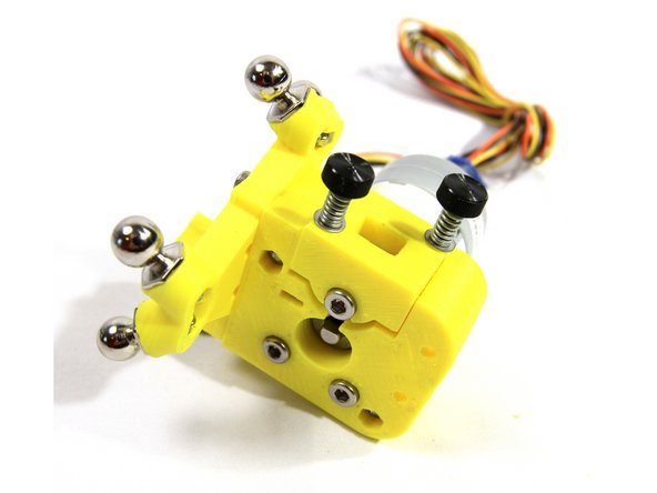
Using the two idler tension screws you prepared earlier, install the idler to the extruder body as shown.
-
The idler can only be installed one way with the bearing screw head facing out as shown.
-
-
-
To repeat: Please read the E3D V6 Assembly Guide before starting assembly of the hot end. Note that we do put the fan on opposite of how E3D installs. That's so the fan air flow is more effectively cooling the Micro Extruder stepper motor.
-
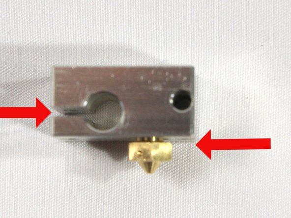
Install the nozzle on the side of the heat block that has the cartridge heater hole closest to its face as shown in the first photo. Screw all the way in then back the nozzle out 1/2 turn. There must be a small gap as shown.
-
Screw the heat break all the way into the heater block as shown in the second photo.
-
Tighten the nozzle to the het break with a 7mm wench.
-
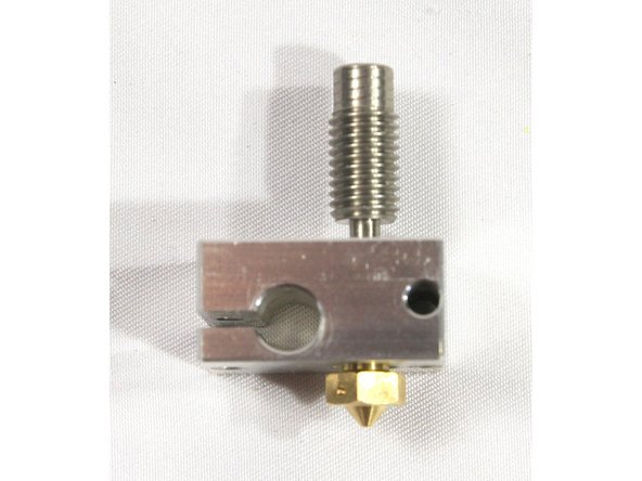
Make sure the short piece of PTFE tubing provided by UltiBots is clean and square on both ends. The openings should not be restricted. Insert the tubing into the heat break as shown in the third photo.
-
-
-
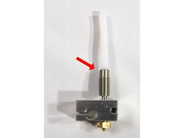
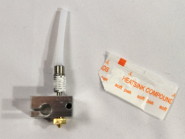
Apply a thin coating of heatsink compound to the heat break threads. Do not get the compound on the unthreaded area. A little goes a long way.
-
Save the remaining compound for later, you will use it when installing the heated bed.
-
Install the heatsink and hand tighten it to the heat break as shown in the second photo.
-
Note that the heatsink must not be tightened against the heater block. There should be about a 3mm gap between these parts as shown.
-
-
-
Make sure the black plastic collar is not installed on the heatsink (circled in the first photo). You will not use this piece.
-
Test fit the heatsink into the extruder as shown. It should be a snug friction fit but should not take extreme force. Use an X-acto knife to remove any burrs or plastic fragments if it does not fit easily.
-
Be careful not to bend the heat break by using too much force. Do not put pressure on the heat block, only the heat exchanger.
-
Remove the hot end after insuring a good fit.
-
-
-
Install the thermistor cartridge in the heater block. The wires should protrude from the side shown in the first photo. The set screw and small Allen wrench are included in the E3D V6 hot end kit. Tighten the set screw until it just touches the cartridge then do one more 1/2 turn.
-
Do not over-tighten the set screw, you will damage the thermistor.
-
Install the cartridge heater with its wires coming out the same side. Align the wires as shown in the second photo. Tighten the clamp with an M3x10 screw until the cartridge is held securely in place.
-
Clip the thermistor lead wires to the thermistor connector as shown in the third photo.
-
The heater cartridge and thermistor must be held in place securely as described above.
-
-
-
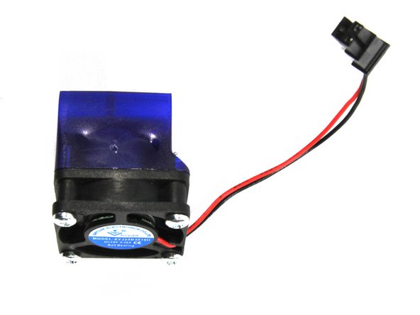
Attach the fan to the fan shroud oriented as shown in the photo.
-
Note that the fan label is facing out - this is opposite of how the E3D V6 guide assembles it. This is done to provide better air flow and cooling over the micro extruder stepper motor.
-
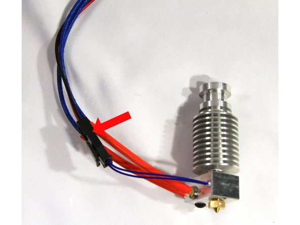
Attach the fan extension wires to the connector as you did for the thermistor in the previous step.
-
-
-
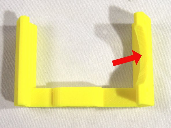
Trim off the corner pads (used to hold the fan bracket to the bed when it was printed) with an X-acto knife. Note the circular cutout indicated by the arrow - clean any plastic residue from it too.
-
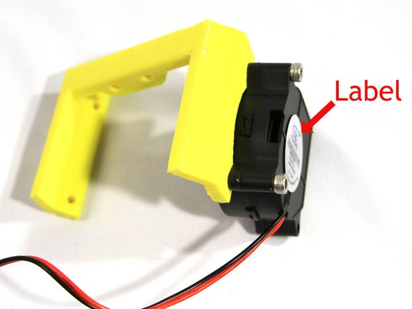
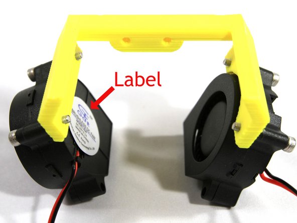
Install a part fan to the fan bracket using two cap screws as shown in the second photo.The round part of the fan will fit into the circular cutout in the fan bracket. Note that the label must face out with the opening directed away from the bracket as shown.
-
These screws are threaded into the plastic so do not over tighten them or you will strip the fan bracket threads.
-
Install the second part fan as shown in the third photo. Its label will face inward.
-
-
-
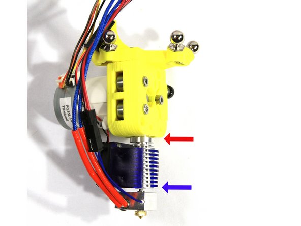
Insert the hot end into the recess in the extruder as shown in the first photo. Note the red arrow showing the hot end fully inserted into the extruder. The screws that attach the part cooling fan bracket will fit through the groove in the hot end so it must not be showing.
-
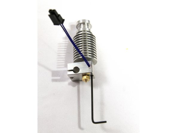
Make sure the PTFE tube is installed in the hot end.
-
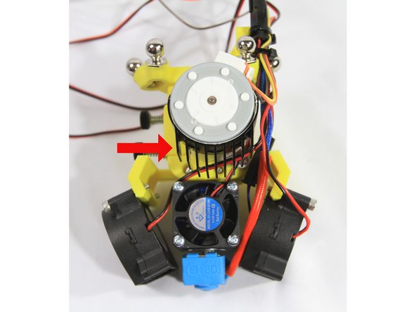
Install the heat exchanger fan shroud with the fan positioned under the stepper motor as shown in the first photo. Note the blue arrow - it shows the bottom of the heat exchanger fan shroud aligned with the first fin on the heat exchanger.
-
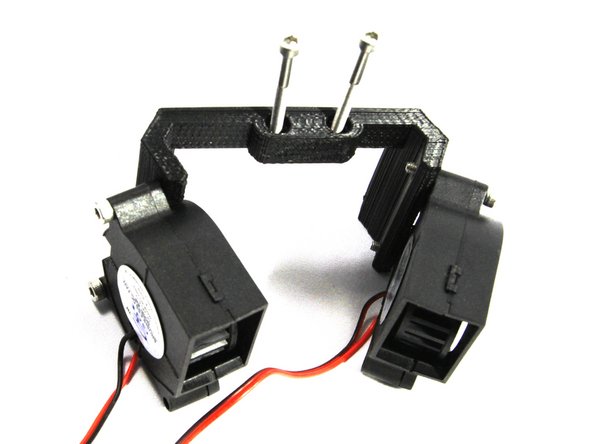
Attach the part cooling fan bracket to the extruder with two cap screws as shown in the second and third photos. These screws must engage the groove in the top of the hot end.
-
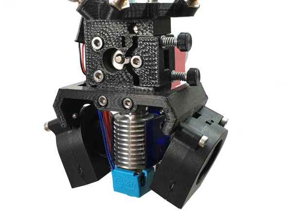
The third photo shows the part completed assembly.
-
Note: you may install the blue silicone sock on the heater block at this time as shown.
-
-
-
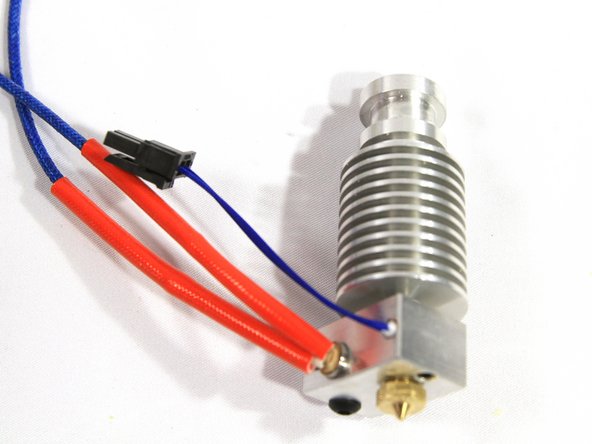
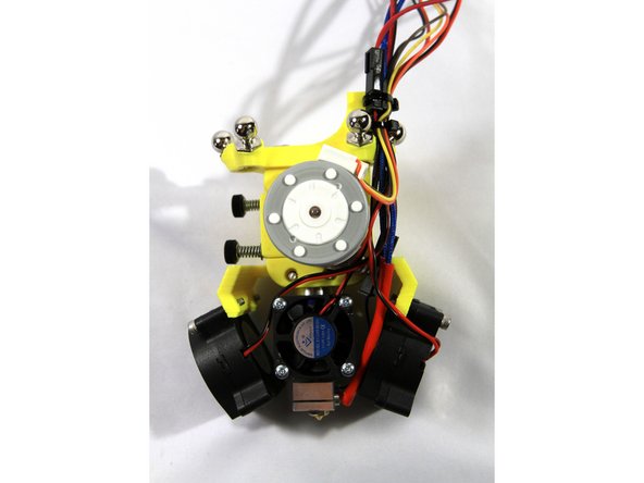
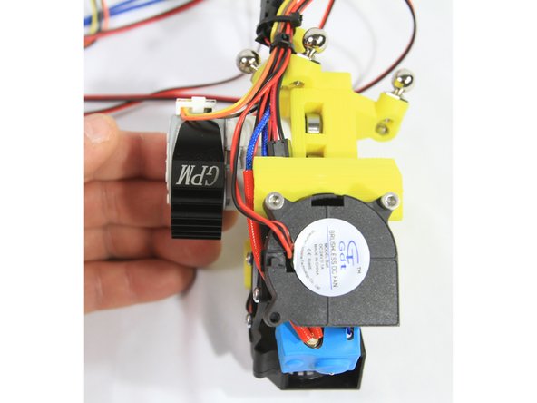
Route all of the wires from the hot end, part cooling fans and heat exchanger cooling fan as shown in the first photo. Then affix them to the wiring post on the effector with two small Zip Ties.
-
The second photo shows a side view of the wire routing.
-
-
-
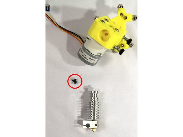
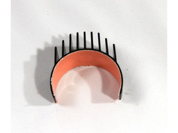
A piece of special thermally conducting tape called Akasa Heat Tape found in the Micro Extruder Motor bag is used to attach the heat sink to the motor
-
Remove the paper protective film from the Akasa Heat Tape and apply the tape to the inside of the heat sink. Trim the excess tape off with an X-acto knife.
-
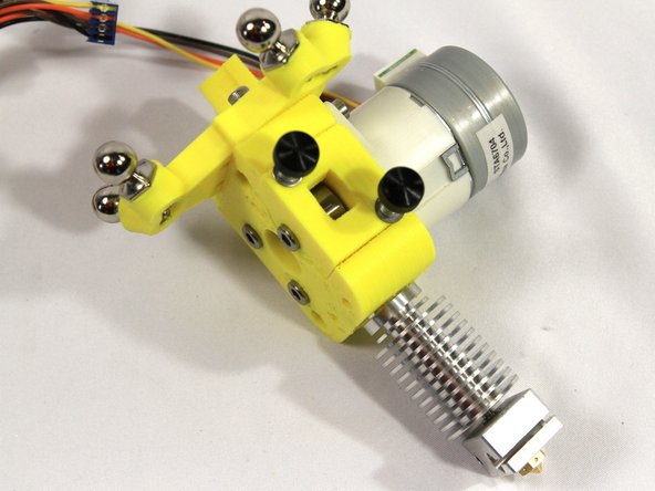
Remove the pink plastic film from the tape and snap the heat sink around the extruder stepper motor oriented down as shown in the second photo.
-
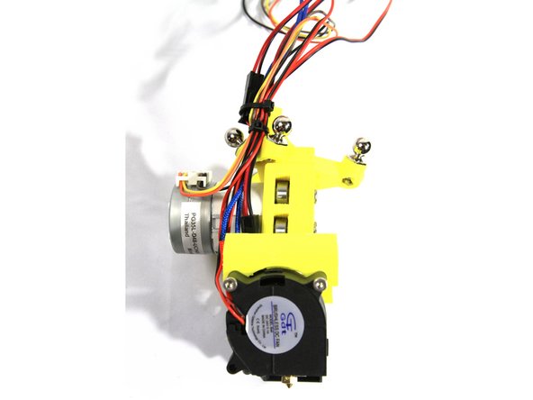
The third photo shows a side view of the completed extruder and hot end assembly.
-
That completes the effector, extruder and hot end assembly. Please read the notes and tips on the D300VS Build Guide Step 63 before continuing with your build.
-


Cancel: I did not complete this guide.
One other person completed this guide.