
Difficulty
Moderate
Steps
8
Time Required
00:30:00 - 01:00:00

In Progress
This guide is currently being written. Reload periodically to see the latest changes.
-
-
Unpack the E3D Titan Aero. Note the card outlined in red. Please read the official assembly documentation first.
-
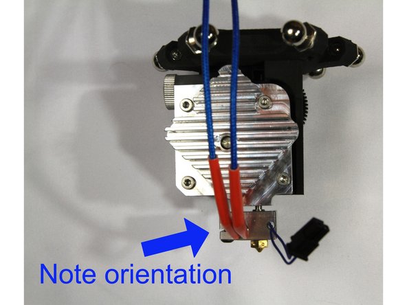
The orientation of the heat block and thermistor and heater cartridge shown in this guide are required to fit the D300VS+ properly.
-
-
-
Install the brass nozzle as described in the E3D guide. Don't forget to leave a 1/2 turn gap.
-
Install the heat brake as described in the E3D guide.
-
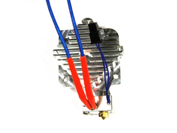
Install the thermistor and heater cartridge with their wire leads coming out of the heater block as shown in the third photo.
-
-
-
It is important to assemble the heater block to the heatsink with the correct orientation as shown in the photo.
-
If your heater block does not align as shown, you can slightly loosen the brass nozzle and position the heater block. Then re-tighten the nozzle.
-
-
-
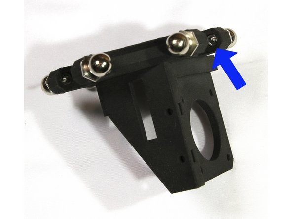
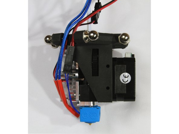
Install six ball studs with M3 nuts on the effector as shown in the first photo.
-
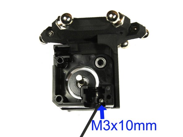
Mount the stepper motor and Titan Body using an M3x10mm screw as shown. Refer to the E3D guide for more details.
-
Note that the stepper motor connector must face up.
This is a good time to check the rectangular holes mentioned in step 8. If the jam nuts don’t fit in the holes, enlarge them now before you connect everything to the effector.
Note on: “Note that the stepper motor connector must face up.” I took this to mean that the cable connector for the stepper needs to be oriented up. This doesn’t match the pictures in Cindy’s build notes and will direct the stepper motor wires into the patch of the printer’s arms. I think the stepper should be mounted such that the connectors face left or right (personally orienting them on the right for easier cable management.
-
-
-
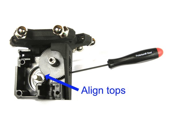
Install the large acetal gear as shown and described in the E3D guide.
-
Insert the M3 grub/set screw in the steel pinion gear and slide it on the stepper motor shaft with the screw facing closest to the stepper. This is described in detail in the E3D guide.
-
Align the top surfaces of the acetal and steel gears as shown and tighten the grub/set screw.
-
You can access the grub/set screw through the slot in the effector as shown in the first photo.
-
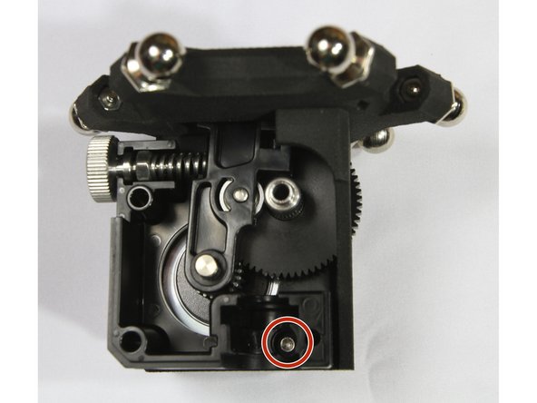
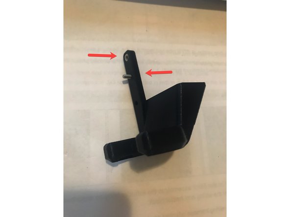
Assemble the idler lever and thumbscrew as described in the E3D guide.
-
You will have to loosen the M3 screw (circled in red) in order to insert the idler lever.
-
Insert the bearing in the heatsink as shown in the third photo.
Aligning the tops of the gears was a little fiddly because the allen wrench used to tighten the set screw wanted to lift up the acetal gear which set a new datum to align to. Maybe future versions of the effector could include a designated access hole for the allen wrench so as to not interfere with the acetal gear while trying to get the two flush with each other.
I just assembled the parts together to establish the position of the metal gear on the stepper then dissassembled to tighten the grub screw.
Jeffrey -
-
-
-
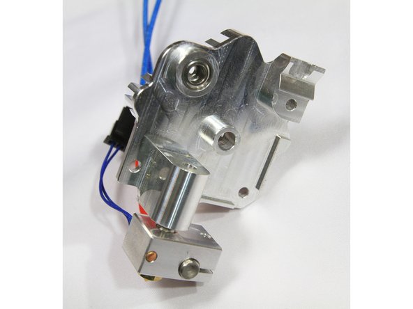
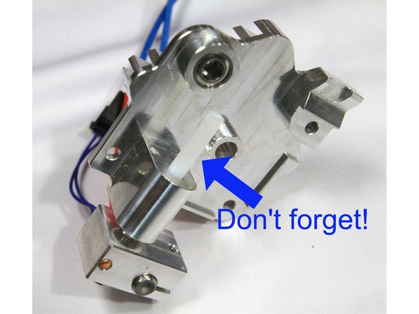
Cut a 23mm long section of PTFE tube and insert it in the heatsink as described in the E3D guide.
-
Install the filament guide for 1.75mm filament as shown in the second photo. The guide must sit flush on the machined aluminum surface.
-
-
-
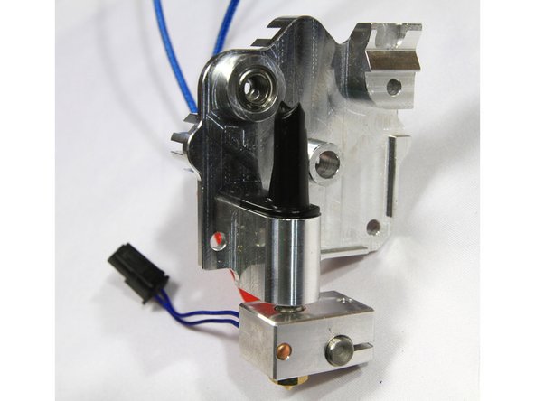
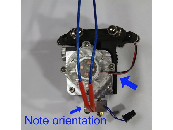
Install the heat sink / heater block assembly to the extruder body as described in the E3D guide. Note the orientation of the wiring and heater block.
-
Install the fan with it's wiring harness oriented as shown in the second photo.
-
Route the wiring between the ball studs as shown in the third photo.
To get the four bolts to hold the extruder together I had to use a total of 7 washers. Two each on the top bolts and bottom left. The bottom right only needed one washer. It might have been fine without it, but I figured it couldn’t hurt. Until the bolt length / spacer size (the effector mount) gets rectified, I’d recommend putting two washers on each bolt for clarity and simplicity.
Whatever’s clever, but if you follow E3D’s instructions then the wires from the thermistor and heat cartridges will be on the other side. This should be noted one way or the other (so simply say that it doesn’t matter). I was scratching my head wondering how I messed it up, tried to reinstall the heatbreak/hotend and then removed and reinstalled the cartridges.
I think it might be better the way you showed it, better access to gear and having the wires tied in two places holds whip upright better.
The guide was written prior to Brad’s product pictures posted on Facebook. Wire management is not critical to the operation of the extruder.
shouldn’t the wires go out the back side ? saw photos that Brad posted on FB.
-
-
-
Find the parts labelled D300VS-Plus Parts Fan Duct and the printed air duct.
-
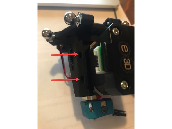
Locate the two rectangular holes on the side near the extruder gear. Insert 2 M3 Jam Nuts. (photo 1)
-
If the nuts don't fit, you may need to widen the hole using a x-acto knife or small flat-head screwdriver.
-
Insert a M3 Jam Nut in the topmost hole of the printed air duct. Then insert the M3X8 bolt into the next hole down. (photo 2)
-
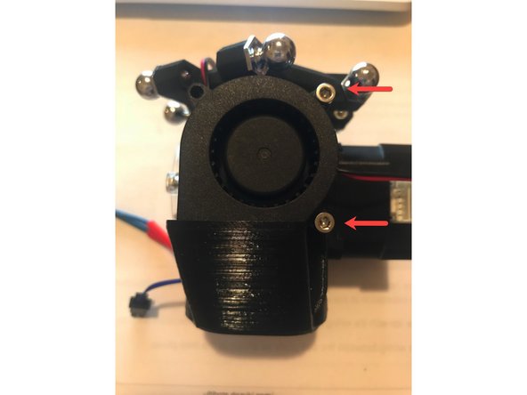
Attach the fan duct to the extruder body matching the topmost round hole (photo 1) with the M3x8 bolt from the previous step. Attach the fan using the M3x18 (top) and then the M3x25 (bottom).
Jake is so right, the nuts don’t fit at all and if the hole isn’t widened all the way down, the nut will get stuck and it will be really hard to remove.
I had significant cleanout to do in the pockets for the nuts and it’s a lot more difficult to do this once everything is assembled. If this is something that is expected for every assembly I think it should be mentioned much earlier in the process before the effector is assembled to any other components. Better yet, I think it should be addressed in the part design so it isn’t an ongoing issue (SLS material choice could also help out with this by switching away from the EX material to something like the standard PA).
-


Cancel: I did not complete this guide.
4 other people completed this guide.
Note: in the E3D instructions it mentions a “spacer” between the motor and the extruder. This spacer is built into the SLS printed effector (with the 6 ball ends for the arms).
Mike Sawyer - Reply