Difficulty
Moderate
Steps
29
Time Required
02:00:00 - 06:00:00
- RAXUS Drone Build Instructions 29 steps

In Progress
This guide is currently being written. Reload periodically to see the latest changes.
Quiz
0
-
-
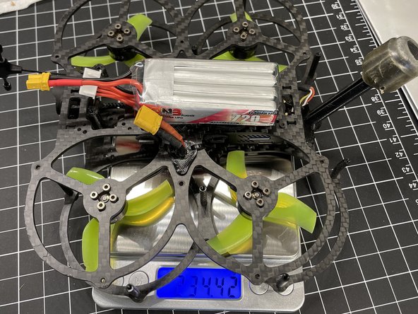
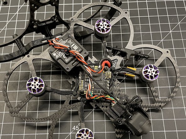
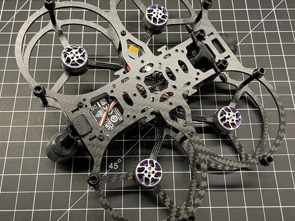
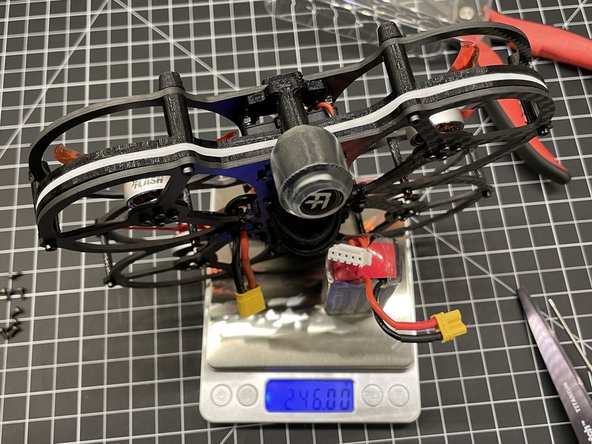
Follow this guide to completion and you will have an awesome flying sub 250g drone!
-
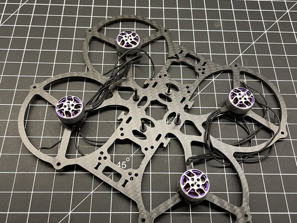
This guide shows the installation of the following components. The motor and FC used were what was available at the time. 1404 4500kv motors and an AIO FC with ESC > 35A is recommened.
-
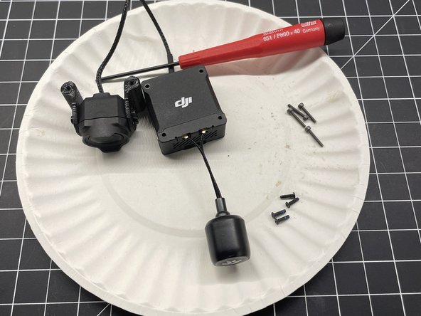
DJI 03 Air Unit
-
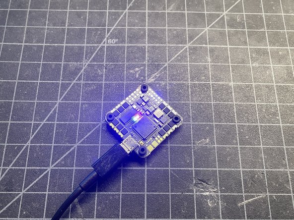
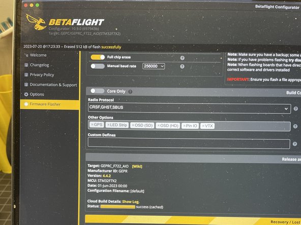
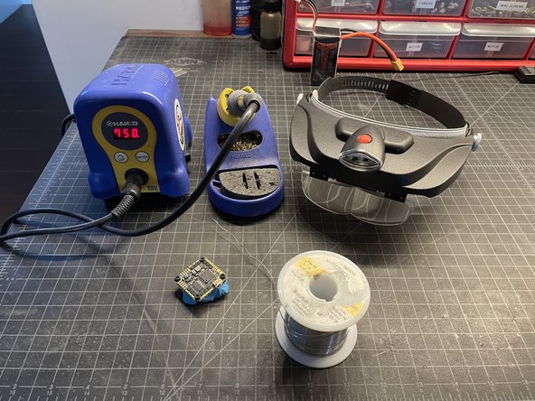
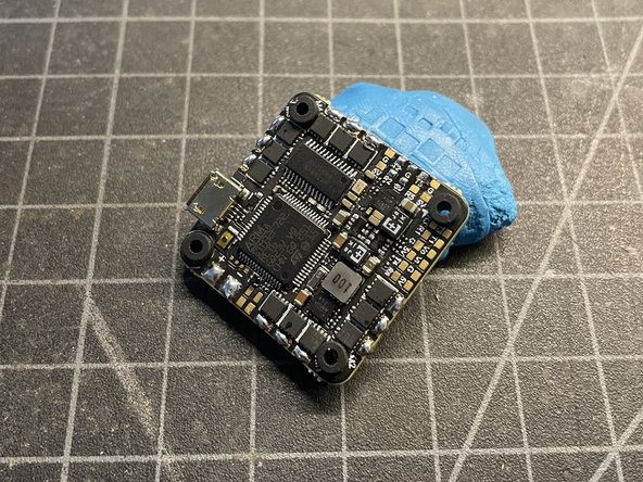
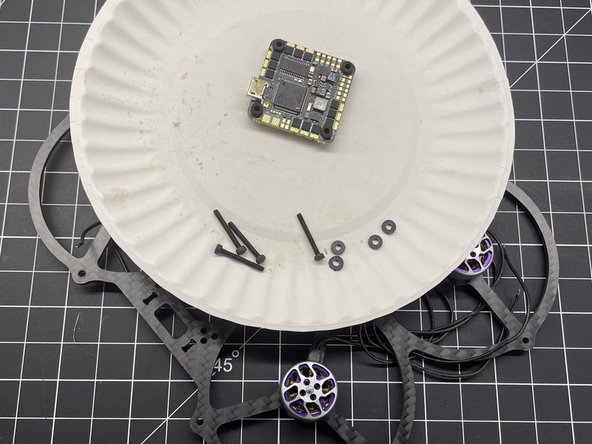
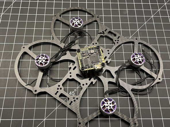
GEP-F722-35A AIO v2
-
FlyFishRC Flash 1404 4500KV Motors (X4)
-
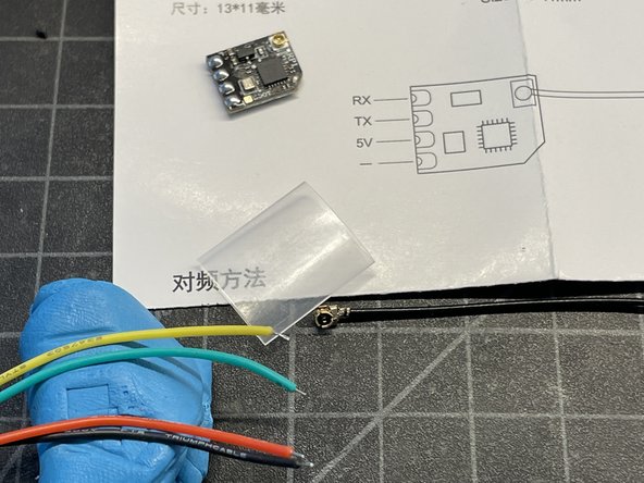
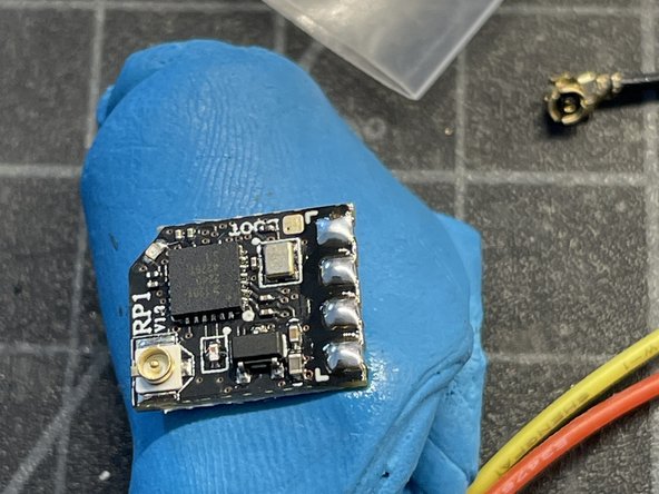
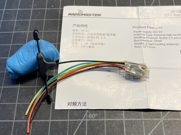
Radiomaster ELRS RX RP1-v2
-
FlyFishRC 40mm Osprey Dual-Band FPV Antenna
-
GNB 4S 720MAH 100C HV Battery
-
-
-
I'm sharing the Raxus to the FPV community as an Open Source Hardware project. It's super fun to fly and a very capable platform for hobbyists and professionals. I want others to enjoy the Raxus. This is my way of giving back to the community!
-
Please note this frame was designed around the DJI 03 Air Unit. Adding a Naked GoPro can tip the scales over 250g. Using a naked 03/Vista, removing LEDs, TPU mounts, and other weight saving techniques may be needed to keep the drone sub 250 with action cams.
-
Thanks for your support - BRadFPV
-
-
-
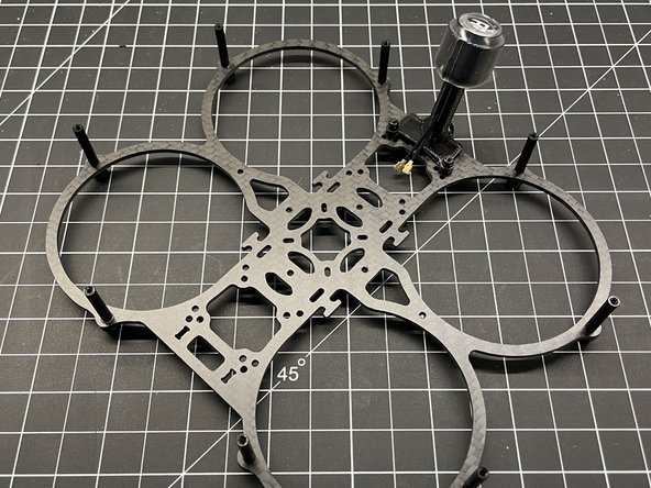
This 2.5" drone frame is named after the Clone Wars planet Raxus in honor of the QAV-Pro Micro drone from which it is derived. I wanted a more versatile frame with a VTX trunk that would securely (screwed down air units) accept many video systems including the DJI 03 Air Unit, Walksnail, HDZero, and analog.
-
The Raxis is an Open Source project and files are here: Thingiverse/6026097
-
There is also a build details here... Rotorbuilds/31175
-
It is a FAA Category 1 small unmanned aircraft that is permitted to operate over people are permitted subject to the following requirements:
-
Weigh 0.55 pounds or less, including everything that is on board or otherwise attached to the aircraft at the time of takeoff and throughout the duration of each operation.
-
Contain no exposed rotating parts that would cause lacerations.
-
No sustained flight over people.
-
-
-
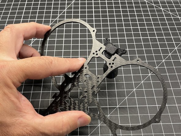
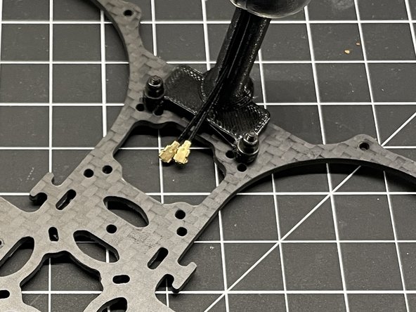
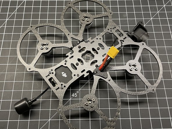
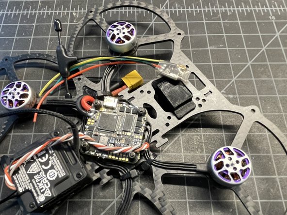
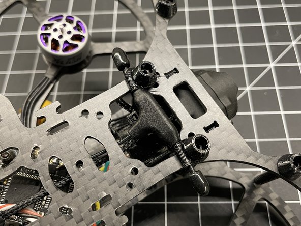
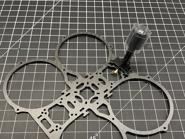
The antenna mount, mounts to the bottom CF plate (the one without motor mounts).
-
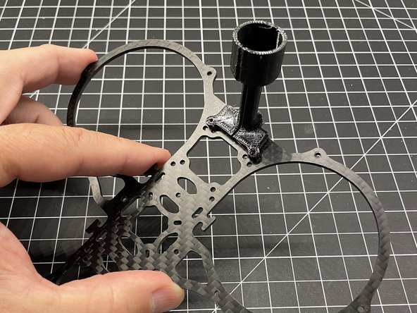
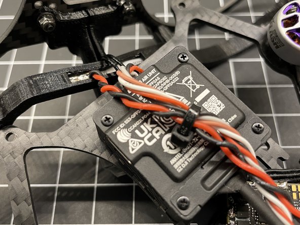
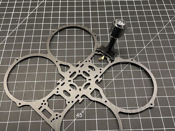
Position the antenna backwards as shown and then rotate it into position. (pic #2)
-
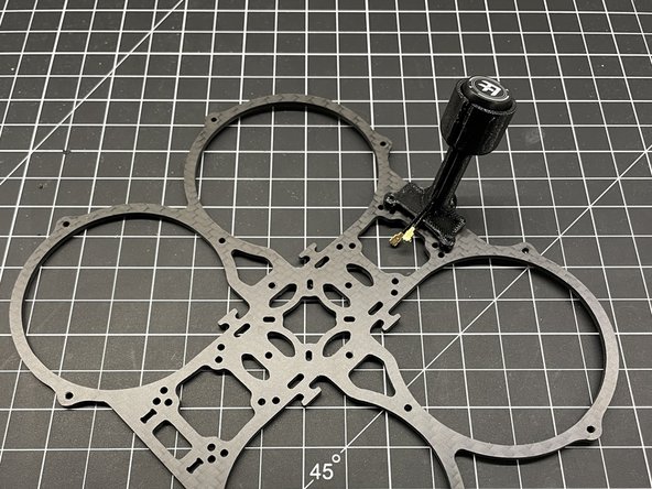
Place the antenna in the mount as shown. Your antenna may be different. The antenna shown is the 40mm Osprey from FlyFishRC for the DJI 03 Air Unit. (pic #3)
-
NOTE: DON'T ADD HEAT SHRINK AS SHOWN - NEW PHOTO NEEDED
-
-
-
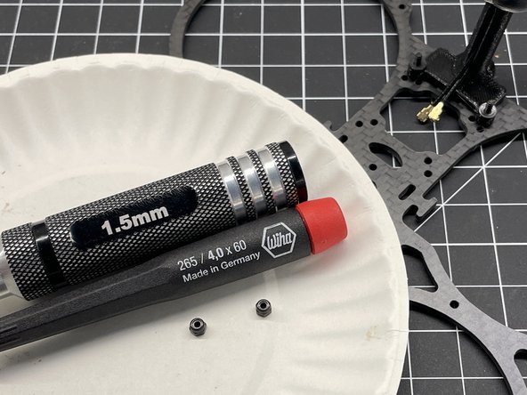
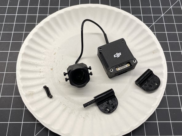
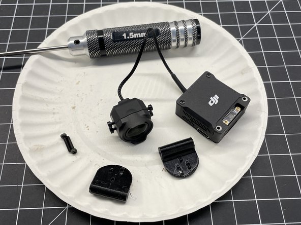
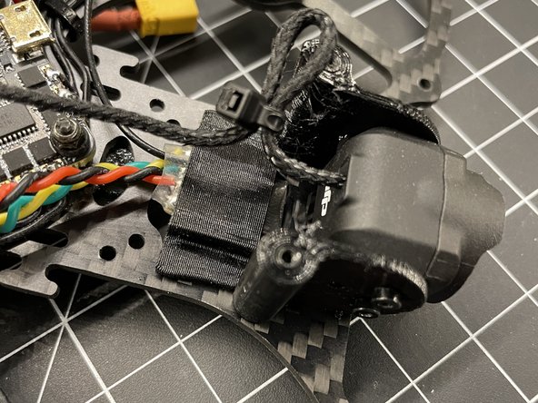
Insert M2 standoff in each TPU camera mounts (pic #1)
-
Remove camera mounting screws and push them into the TPU mounts (pic #2)
-
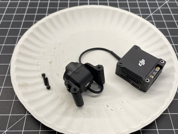
Screw camera mounts to camera as shown (pic #3)
-
The TPU mount allows for angle adjustment. Make sure the DJI printed logo is facing up with the TPU adjustment slot below logo
-
-
-
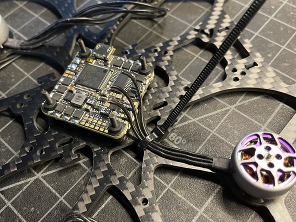
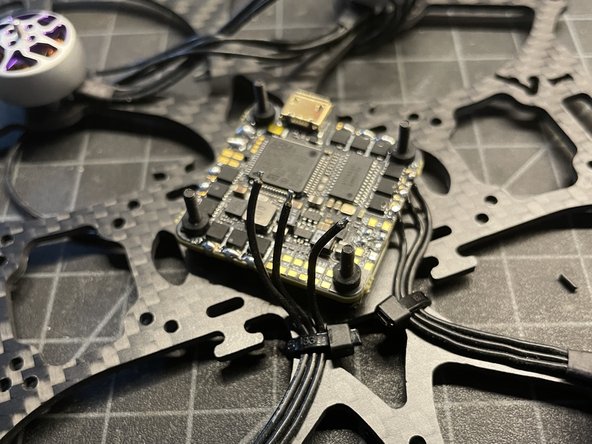
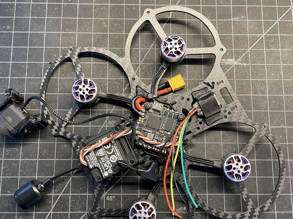
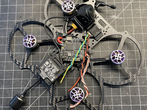
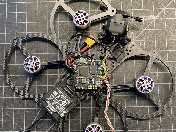
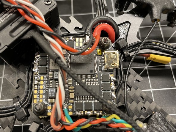
Trim twisted wires to length. Cut approx 2mm insulation & pre-tin wires. Solder wires to FC as shown
-
Insert Air Unit power/video wire in the FC.
-
NOTE: MAKE SURE THE SBUS (YELLOW) WIRE IS REMOVED IF YOU ARE NOT USING THE DJI REMOTE
-
DON'T POWER AIR UNIT WIRE UNTIL FINAL STEPS AS YOU MAY OVERHEAT & POSSIBLY DAMAGE THE UNIT
-
-
-
FIND THE MIDDLE LED +/- CONDUCTOR TERMINALS AND POSITION THE LED COB STRIP IN THE MOUNT SO THE LEADS ARE CENTERED IN THE TPU MOUNT
-
Trim approx 5mm insulation of LED lead wires, pre-tin, and solder to +/- terminals on LED (pic #1)
-
You will have to burn away the adhesive over the LED contacts with the solder iron before tinning the pads and attaching the lead wires
-
Attach the LED TPU mount to the standoffs on the bottom plate as shown (pic #2)
-
Twist, trim insulation, pre-tin, and solder LED lead wires to the VBAT terminals (pic #3)
-
CAUTION: MAKE SURE YOU HOLD VBAT LEADS TO FC WHILE ADDING THE LED LEAD WIRES. CONSIDER ASKING FOR ANOTHER SET OF HANDS
-
-
-
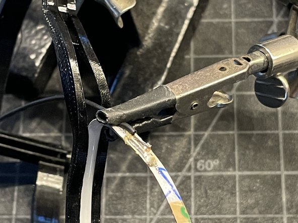
Place heat shrink over the antenna mount. (pic #1) NEW PICTURES NEEDED
-
Use a lighter or heat gun to tighten the heat shrink around the antenna. This is a very durable mounting solution. (pic #2)
-
If your antenna has a significantly smaller diameter, you can trim the edges of the TPU print with side cutters or scissors. If it is significantly wider... you can try to stretch the heat shrink with long needle nose pliers or similar.
-
-
-
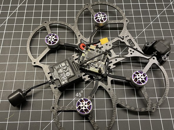
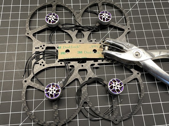
Remove backing from Dual Lock (pic #1)
-
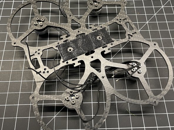
Position Dual Lock over FC screw holes and apply pressure to secure (pic #2)
-
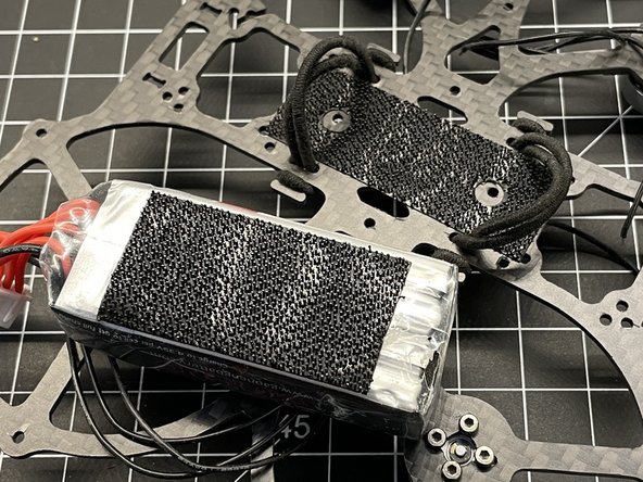
Cut Dual lock into 3 long strips and secure to battery so there is a center channel missing. This will improve LIPO adhesion by avoiding contact with FC screws. NEW PICTURE NEEDED
-
Lastly hook 2 elastic bands thru the frame and back over the hook as shown (zoom in pic #3)
-
-
-
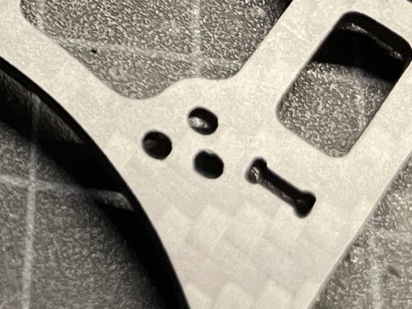
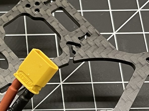
ERRATA...
-
Raxus frame going forward will not have dog bone cutout for 1mm CF camera mounts. CF mounts are inflexible compared to TPU camera mounts (pic #1)
-
This guide used a non production frame with a cut blemish (pic #2)
-
RX mount is not installed correctly... it should be rotated 180 degrees - new picture needed
-