
Difficulty
Moderate
Steps
8
Time Required
00:30:00 - 01:00:00

In Progress
This guide is currently being written. Reload periodically to see the latest changes.
Quiz
0
-
-
Unpack the E3D Titan Aero. Note the card outlined in red. Please read the official assembly documentation first.
-
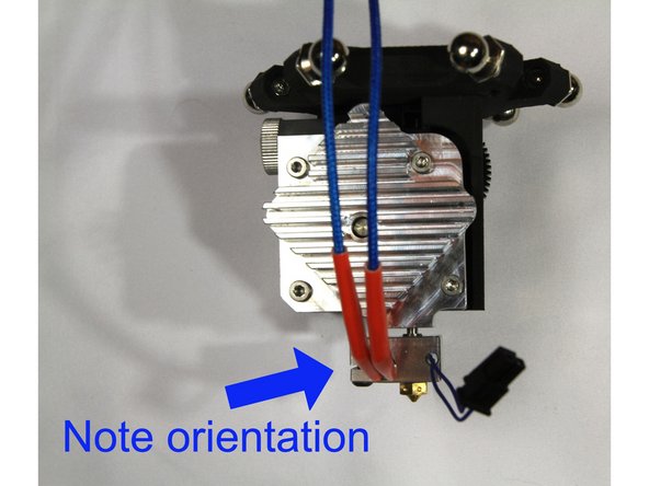
The orientation of the heat block and thermistor and heater cartridge shown in this guide are required to fit the D300VS+ properly.
-
-
-
Install the brass nozzle as described in the E3D guide. Don't forget to leave a 1/2 turn gap.
-
Install the heat brake as described in the E3D guide.
-
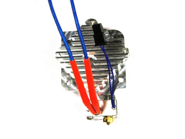
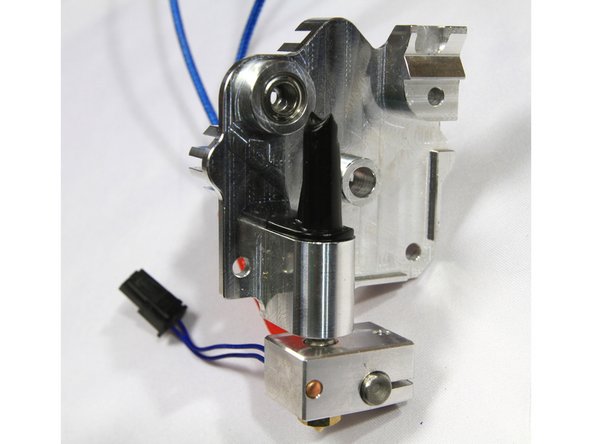
Install the thermistor and heater cartridge with their wire leads coming out of the heater block as shown in the third photo.
-
-
-
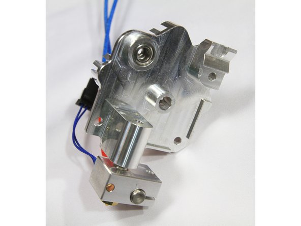
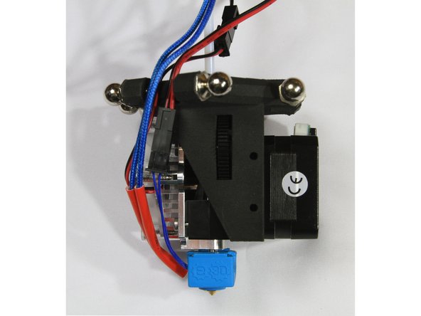
It is important to assemble the heater block to the heatsink with the correct orientation as shown in the photo.
-
If your heater block does not align as shown, you can slightly loosen the brass nozzle and position the heater block. Then re-tighten the nozzle.
-
-
-
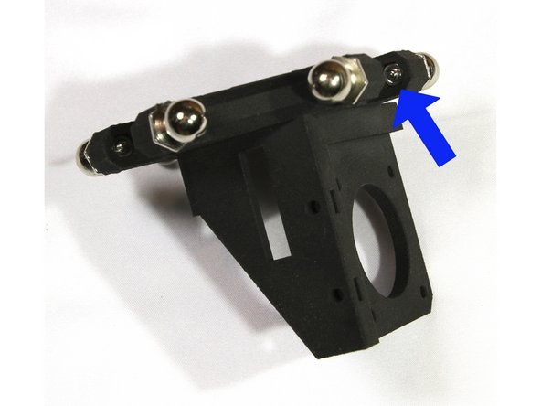
Install six ball studs with M3 nuts on the effector as shown in the first photo.
-
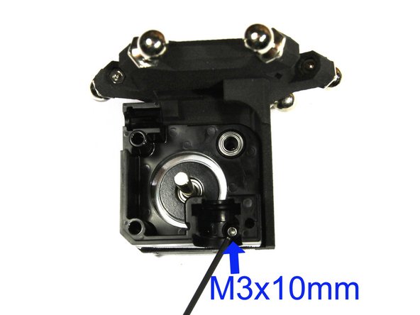
Mount the stepper motor and Titan Body using an M3x10mm screw as shown. Refer to the E3D guide for more details.
-
Note that the stepper motor connector must face up.
-
-
-
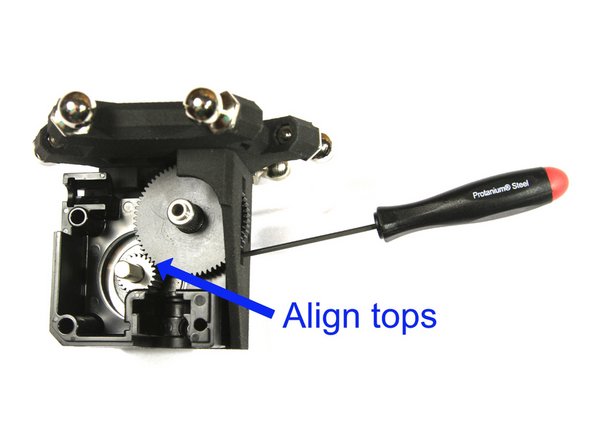
Install the large acetal gear as shown and described in the E3D guide.
-
Insert the M3 grub/set screw in the steel pinion gear and slide it on the stepper motor shaft with the screw facing closest to the stepper. This is described in detail in the E3D guide.
-
Align the top surfaces of the acetal and steel gears as shown and tighten the grub/set screw.
-
You can access the grub/set screw through the slot in the effector as shown in the first photo.
-
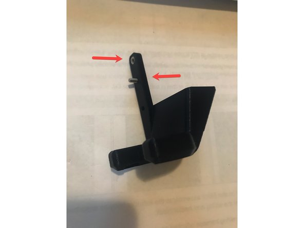
Assemble the idler lever and thumbscrew as described in the E3D guide.
-
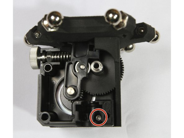
You will have to loosen the M3 screw (circled in red) in order to insert the idler lever.
-
Insert the bearing in the heatsink as shown in the third photo.
-
-
-
Cut a 23mm long section of PTFE tube and insert it in the heatsink as described in the E3D guide.
-
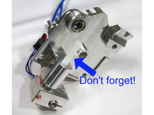
Install the filament guide for 1.75mm filament as shown in the second photo. The guide must sit flush on the machined aluminum surface.
-
-
-
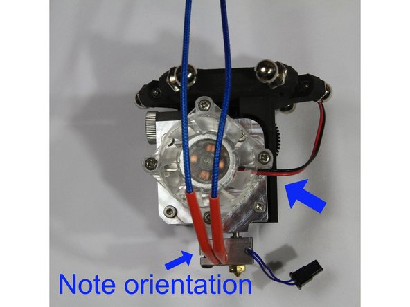
Install the heat sink / heater block assembly to the extruder body as described in the E3D guide. Note the orientation of the wiring and heater block.
-
Install the fan with it's wiring harness oriented as shown in the second photo.
-
Route the wiring between the ball studs as shown in the third photo.
-
-
-
Find the parts labelled D300VS-Plus Parts Fan Duct and the printed air duct.
-
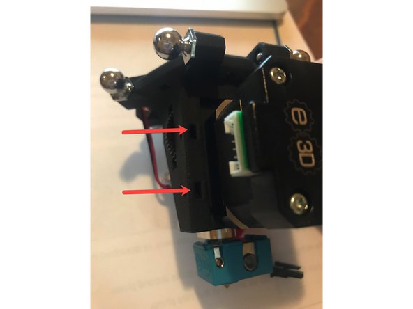
Locate the two rectangular holes on the side near the extruder gear. Insert 2 M3 Jam Nuts. (photo 1)
-
If the nuts don't fit, you may need to widen the hole using a x-acto knife or small flat-head screwdriver.
-
Insert a M3 Jam Nut in the topmost hole of the printed air duct. Then insert the M3X8 bolt into the next hole down. (photo 2)
-
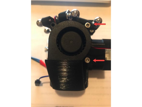
Attach the fan duct to the extruder body matching the topmost round hole (photo 1) with the M3x8 bolt from the previous step. Attach the fan using the M3x18 (top) and then the M3x25 (bottom).
-


Cancel: I did not complete this guide.
4 other people completed this guide.